Service technicians have no problem recognising breakdowns and carrying out machine diagnostics, CLAAS Jaguar Fault Codes DTC, plus they are familiar with equipment from a variety of manufacturers.
 Claas Jaguar is a self-propelled forage harvester that is built by German farm machinery company Claas and is powered by a DaimlerChrysler diesel engine. Models are identified by numbers; current models are numbered 830, 850, 870, 890, and 900. Launched in 2007 were the Jaguar 950, 960, 970, and 980. The Claas Jaguar Green Eye is quite a new addition. The current 900 model currently being sold in Europe is known as the Claas Jaguar 900 Green Eye.
CLAAS Jaguar Tractor Fault Codes List
Code Module Fault Operating state Troubleshooting
E-1 Device CAB oil pressure engine too poor
E-2 Device CAB Oil Level engine too low
E-3 Unit CAB Water pump defective Charging Control lights and goes out. Test drive water pump and generator. Check control charge on generator
E-4 CAB Temperature cooling water too high
E-5 CAB hydraulic temperature Coil too high
E-6 CAB Tighten the handbrake
E-8 Electric Hydraulic First drive running of the EFA Wrong voltage potentiometer supply of movement
E-11 Apparatus CAB pressure hydraulics Coil or oil level is too low
E-12 Apparatus CAB Temperature charge air too high
E-13 Metal detector ESR defective
E-14 ESR Metal detector interrupt
E-15 Apparatus CAB Reserve CAB
E-16 ESR still connected adapter box SFM (Note: SFM self-propelled mower) When necessity check configuration (SFH or SFM).
E-17 Numbers of revolutions ESR Sensor feeder defective Check plug to compound sensor and cable compound.
E-18 Numbers of revolutions ESR Sensor feeder defective Check plug to compound sensor and cable compound.
E-19 Apparatus CAB Hydraulic drive motor Coil not complies configuration
E-20 Ellectric Hydraulic First drive running of the EFA new module EFA absolutely necessary potentiometer study movement of the lever This message appears after installing a new EFA module when the ignition. After learning potentiometers arm and hydraulic motion flow this message no longer appears. 1. Study potentiometer movement of the lever 2. Study hydraulic flows through CDS system Hydraulic oil should have labor temperature. meaning voltage pressure sensors should be < 1.2 V.
E-25 ESR fault downstream hydraulic pump feeder
E-27 Electric Hydraulic First drive running of the EFA Defective valve output PWM trailer brakes
E-30 In ESR Valves stop permanently energized
E-32 CAB CAN-Bridge Module defective Check power module. Check strength landing and contact conclusions.
E-33 ESR ESR module defective. Check power module. Check strength landing and contact conclusions.
E-34 AutoContour CAC module outline faulty system Check power module. Check strength landing and contact conclusions.
E-36 GGS GGS Defect Test power module. Check strength landing and contact conclusions.
E-37 Electrical Hydraulic First drive running of the EFA EFA faulty module Emergency stop: During this work It indicates a defect power module output. It should be shut down. The movement of the machine no more provided possible. Turn off the machine and restart, if the fault no more It appears, in another module procedure, otherwise. If not, replace module.
E-38 Control Unit valve defective
E-39 ATP reserve, autopilot
E-40 First drive running of the EFA Faulty valve hydraulic pump Emergency mode: machine moves only reversing at speeds OK. 2 km / h at the 2nd Transfer 1 km / h in the 1st transmission. When you identify short the closure of the valve It made an emergency Stop the movement over impossible. flap impossible to govern: Check cable Connect to valve. Check the module output. Measure resistance coil range values: 6 – 12 ohms Check plug to compound valve.
E-41 First drive running of the EFA Faulty electromagnetic hydraulic valve engine Limited exploitation: Steer until Max. 7 km / h on the 1st transmission, 12 km / h on the 2nd transfer flap mpossible to govern: Check cable module connection to the valve for a short circuit or breakage. Check the module output. measure esistance coil range values: 6 – 12 ohms Check plug to compound valve.
E-42 First drive running of the EFA Faulty third magnet electromagnetic valve Emergency Stop: The machine moves on coast to stop, further movement is not provided possible. flap impossible to govern: Check cable module connection to the valve for a short circuit or breakage. Check the module output. measure resistance coil range values: 6 – 12 ohms Check plug to compound valve.
E-43 First drive running of the EFA Defect electromagnetic pump valve motion ago Emergency mode: The machine moves only forward at approx. 2 km / h at the 2nd transmission 1 km / h on the 1st gear. When you identify short the closure of the valve It made an emergency. Stop the movement over impossible. flap impossible to govern: Check cable module connection to the valve for a short circuit or breakage. Check the module output. measure resistance coil range values: 6 – 12 ohms Check plug to compound Valve.
E-44 CAB Out of order communication engine system No CAN bus to module ADM. The module works wrong. Check power modules. Check cable trunk to modules (terminals).
E-45 Grinder GGS not in the initial position
E-46 First drive running of the EFA Faulty lever potentiometer of movement Emergency mode: The car moves with speed 1 km / hr only in the forward direction.(Identification of areas movement through neutral switch position and the switch Reverse) Potentiometer movement of the lever It is in the form double potentiometer.
E-46 Check cable set to module potentiometer on open or short circuiting. Potentiometer Motion 2 issues opposite signal sum with which the signal potentiometer Motion 1 is always must have permanent value. If the total signal is not in within 7.3 – 7.5, the potentiometer movement of the lever defective. Example: Signal 1 = 4.0 V Signal 2 = 3.4 V> Amount: 4.0 + 3.4 = 7.4 B => potentiometer order. Signal 2 = 1.0 => Amount: 4.0 + 1.0 = 5.0 B => potentiometer defective measure potentiometer.
E-47 First drive running of the EFA exceeded tolerance lever potentiometer of movement Unusual behavior movement. No, the final speed. Despite the return of movement of the lever ago speed reduction initially not made (Slow response). Only the issue of a code, the behavior of the motion is not changes. Potentiometer movement of the lever It is in the form double potentiometer: permissible meaning potentiometer Motion 1:
Neutral Situation: 3,8 – 4.2V Next: 6.9 – 7.3 in Previous: 0.8 – 1.2 V Potentiometer Motion 2 issues opposite signal sum with which the signal potentiometer Motion 1 is always must have permanent value. If the total signal is not in within a predetermined range, lever potentiometer of movement defective.
E-48 In the feed ESR Metal device The delivery device It stands load metal detector. Remove the metal. Is not fault in sense of the word.
E-49 ESR Stop slip clutch consoles STB is turned off. Post without overload: Check cable set and to console her. Check sensor rotation speed prefix.
E-50 ESR does not recognize the adapter SFM box The module identifies the ESR speed sensors Rotation Disco 8500, but 5 are absent from adapter box. Female compound: Check 13 pin connector on the driver site (corrosion). Open or short closing signal wire to the ESR module.
E-51 The level of coolant the water is too low Refuel cooling water. Cable set or plug cause short short to ground.
E-52 ESR No recognition rotation speed feeder Fault can be issued in multiple without reversing causes. When submitting a feed the device is switched off after the issuance of reports malfunction. Check plug to compound speed sensor rotation. Check 13 pin connector on the driver site (corrosion). Open or short closing signal wire to the ESR module.
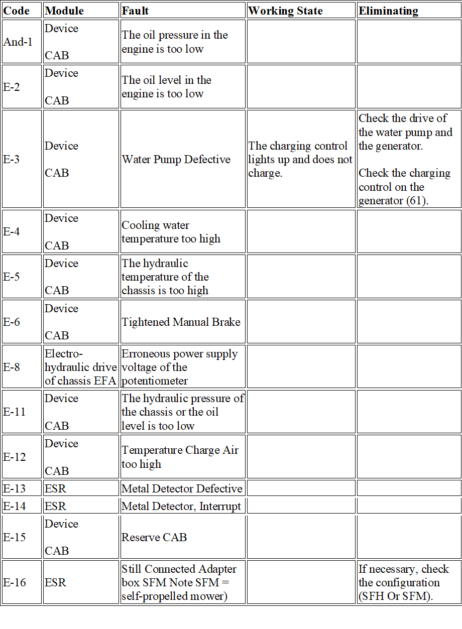
| Code | Module | Fault | Working State | Eliminating |
| And-1 | Device
CAB |
The oil pressure in the engine is too low | ||
| E-2 | Device
CAB |
The oil level in the engine is too low | ||
| E-3 | Device
CAB |
Water Pump Defective | The charging control lights up and does not charge. | Check the drive of the water pump and the generator.
Check the charging control on the generator (61). |
| E-4 | Device
CAB |
Cooling water temperature too high | ||
| E-5 | Device
CAB |
The hydraulic temperature of the chassis is too high | ||
| E-6 | Device
CAB |
Tightened Manual Brake | ||
| E-8 | Electro-hydraulic drive of chassis EFA | Erroneous power supply voltage of the potentiometer | ||
| E-11 | Device
CAB |
The hydraulic pressure of the chassis or the oil level is too low | ||
| E-12 | Device
CAB |
Temperature Charge Air too high | ||
| E-13 | ESR | Metal Detector Defective | ||
| E-14 | ESR | Metal Detector, Interrupt | ||
| E-15 | Device
CAB |
Reserve CAB | ||
| E-16 | ESR | Still Connected Adapter box SFM Note SFM = self-propelled mower) | If necessary, check the configuration (SFH Or SFM). |
| Code | Module | Fault | Working State | Eliminating |
| E-17 | ESR | The sensor of the speed of the feeding device is defective | Check the plug connection on the sensor and cable connections. | |
| E-18 | ESR | The sensor of the speed of the feeding device is defective | Check the plug connection on the sensor and cable connections. | |
| E-19 | Device
CAB |
The hydraulic motor of the chassis drive does not match the configuration of the | ||
| E-20 | Electrohydraulic drive of chassis EFA | New module EFA = > It is necessary to study the potentiometer of the movement lever | This message appears after you install a new module EFA When the ignition is turned on.
After examining the potentiometers of the movement lever and hydraulic flows, this message no longer appears. |
1. Study Spinner Lever Movement
2. Study of Hydraulic flows Through the system CDS The hydraulic oil must Have a working temperature. Pressure sensor voltage values must be < 1.2 v. |
| E-25 | ESR | Malfunction on the flow of the hydraulic pump of the feeding device | ||
| E-27 | Electrohydraulic drive of chassis EFA | Valve exit defect
PWM Trailer Brakes |
||
| E-30 | ESR | The quick stop valve is constantly energized | ||
| E-32 | Device
CAB |
Module CAN-Bridge
Defective |
Check the power supply of the module.
Check the landing strength and pin pins. |
| Code | Module | Fault | Working State | Eliminating |
| E-33 | ESR | Module ESR Defective | Check Power supply Module.
Check the landing strength and pin pins. |
|
| E-34 | Autopath
Cac |
Module Contour System Defective | Check Power supply Module.
Check the landing strength and pin pins. |
|
| E-36 | GGS | Defect Module GGS | Check Power supply Module.
Check the landing strength and pin pins. |
|
| E-37 | Electro-hydraulic drive of chassis EFA | Module EFA Defective | Emergency STOP:
This indicates a defect in the module’s power output during operation. should be disconnected. Driving is no longer possible. |
Turn off the machine and run again, if the malfunction no longer appears, the module is still in order, в Otherwise replace the module. |
| E-38 | KSR | Module Management Damper Defective | ||
| E-39 | ATP | Reserve, Autopilot | ||
| E-40 | Electro-hydraulic drive of chassis EFA | Defective Valve Hydraulic | Emergency mode:
The machine moves only the rear Progress With Speed Ok. 2 km/hour on the 2nd gear and 1 km/h on the 1st transfer. When the short-circuit is identified, the valve is stopped and the movement is no longer possible. |
Flap That’s impossible Manage:
Check the cable connection to the valve. Check the module output. Measure coil resistance, range of values: 6-12 Ohm Check the plug connection on the valve. |
| Code | Module | Fault | Working State | Eliminating |
| E-41 | Electro-hydraulic drive of chassis EFA | Malfunctioning solenoid valve of hydraulic motor | Limited Operation:
Movement to Max. 7 km/hour on the 1st transfer, Approx. 12 km/h on 2nd gear |
Flap That’s impossible Manage:
Check the cable connection of the module To Short circuit or breakage. Check Output Module. |
| Measure coil resistance, range of values: 6-12 Ohm | ||||
| Check the plug connection on the valve. | ||||
| E-42 | Electrohydraulic drive of chassis EFA | 3-nd magnet of the electromagnetic valve is defective | Emergency STOP:
The machine moves by inertia to the stop, further movement is not possible. |
Flap That’s impossible Manage:
Check the cable connection of the module To Short circuit or breakage. Check Output Module. |
| Measure coil resistance, range of values: 6-12 Ohm | ||||
| Check the plug connection on the valve. |
| Code | Module | Fault | Working State | Eliminating |
| E-43 | Electro-hydraulic drive of chassis EFA | Defect of the electromagnetic valve of the hydraulic pump for the movement back | Emergency mode:
The machine moves only forward at a speed Ok. 2 km/hour on the 2nd gear and 1 km/hour on the 1st transfer When the short-circuit is identified, the valve has an emergency stop, the movement of more That’s impossible. |
Flap That’s impossible Manage:
Check the cable connection of the module To Short circuit or breakage. Check Output Module. |
| Measure coil resistance, range of values: 6-12 Ohm | ||||
| Check the plug connection on the valve. | ||||
| E-44 | Device
CAB |
The engine’s communications system is out of order | Missing bus CAN To Module ADM.
Module It’s working Incorrectly. |
Check the power supply of the modules. Check the cable trunk to the modules (conclusions). |
| E-45 | GGS | Grinding Stone not in the original position | ||
| E-46 | Electro-hydraulic drive of chassis EFA | Defective Potentiometer Lever Movement | Emergency mode:
The machine moves at a speed of 1 km/hour only in the direction of forward. (Movement direction recognition by means of neutral position switch and reversing switch) |
The potentiometer of the movement lever is made in the form of a double potentiometer. The fault signal is issued in the following cases:
Incorrect polarity of the potentiometers of movement, breakage of a cable set, defective contact strip of a potentiometer. |
| Eliminating: | ||||
| Check the voltage of the potentiometer of movement, check the plug connection on the potentiometer. |
| Code | Module | Fault | Working State | Eliminating |
| E-46 | Check the cable set of the module to the potentiometer on the breakage or short circuit.
The potentiometer of Motion 2 produces the opposite signal, the sum of which with the signal of the potentiometer of motion 1 should always have constant value. If the total signal does not lie within the range of 7.3-7.5 B, the potentiometer of the movement lever is defective. Example: Signal 1 = 4.0 in Signal 2 = 3.4 in = > Amount: 4.0 + 3.4 = 7.4 in = > potentiometer is OK. Signal 2 = 1.0 in = > Amount: 4.0 + 1.0 = 5.0 in = > Potentiometer defective Measure Potentiometer. |
| Code | Module | Fault | Working State | Eliminating |
| E-47 | Electro-hydraulic drive of running
Part EFA |
Lever potentiometer tolerance exceeded | Unusual behavior when driving.
The final speed is not reached. |
The potentiometer of the movement lever is made in the form of double
Spinner: |
| Despite the return of the lever of movement back speed reduction is not performed at first
(Slow Reaction). |
Valid Values Spinner Movement 1: | |||
| Speedstar Fur: Only code delivery,
Behavior Movement Not Changes. |
Neutral Position: 3.8-
4.2 In Forward: 6.9-7.3 in |
|||
| Back: 0.8-1.2 in | ||||
| If there is an excess of values forward or backward on the mechanical end positions of the movement lever, it is necessary to align the control system of the movement lever potentiometer. | ||||
| The potentiometer of Motion 2 produces the opposite signal, the sum of which with the signal of the potentiometer of motion 1 should always have constant value. | ||||
| If the total signal does not lie within the specified range, the potentiometer of the movement lever is defective. | ||||
| Speedstar Fur: Check the angle sensor and the traction system, BT 31A POS 50, 10, 47 |
| Code | Module | Fault | Working State | Eliminating |
| E-48 | ESR | Metal In the Flow Device | The feeding device stands, the metal detector has worked. | Remove the metal.
is not a malfunction in the sense of the word. |
| E-49 | ESR | Stop slipping clutch of Coupling Consoles | Console Disables. | Message without Overload:
Check the cable set to the console and from it. Check the speed sensor of the console. |
| E-50 | ESR | Adapter box not recognized SFM | Module ESR Recognize speed sensors Disk 8500, but there are no 5 in the adapter box. | Plug Connection:
Check the 13-pole plug on the driver’s site (corrosion). Breakage or short-circuit of the signal wire to the module ESR. |
| E-51 | Device
CAB |
The cooling water level is too low | Refuel Cooling Water.
The cable kit or plug causes a short circuit to be Mass. |
|
| E-52 | ESR | No speed recognition of the feeding device | A fault message can be issued with multiple reversal without cause.
When feeding, the feeder is disconnected after the fault message is issued. |
Check the plug connection on the speed sensor.
Check the 13-pole plug on the driver’s site (corrosion). Breakage or short-circuit of the signal wire to the module ESR. When installing the console Kemper Module must be installed ESR 014 213.4 (500 Ms.). |
| Code | Module | Fault | Working State | Eliminating |
| E-53 | ESR | Short Circuit of the external key switch reversing | When the main drive is switched on, the machine reverses simultaneously. | Check the reversal key switch on the drawer near the wheel (short circuit). |
| Check the key switch in the Multifunkcionaln Handle (short circuit). |
| Code | Module | Fault | Working State | Eliminating |
| E-54 | Electro-hydraulic drive of chassis EFA | Interruption of study due to exceeding the time limit or incorrect starting condition | Normal operation:
The error signal is given only when examining the potentiometer of the movement lever. |
1st opportunity:
When starting the study there were incorrect conditions: |
| The movement lever is not in a neutral position. | ||||
| The lever of motion in the study was initially given back. | ||||
| The potentiometer of movement at the start of the study is outside the tolerance zone. | ||||
| 2nd Possibility: | ||||
| During 15 seconds do not recognized the change of the signal of the potentiometer of motion, this study is interrupted. | ||||
| At the same time the code e-180 is issued, because acceptable values of the potentiometer are not achieved. | ||||
| If there are no errors concerning the driving drive before memorizing the signal, you can continue to operate the machine on the previous parameter values. | ||||
| But if the study was conducted on the basis of the surfaced previously reported failure, then the study should be repeated until it is successfully completed, otherwise the machine can only work in emergency mode. |
| Code | Module | Fault | Working State | Eliminating |
| E-55 | Device
CAB |
There is no signal of traffic switch on roads | ||
| E-56 | ESR | The speed sensor of the left Mowing The machine reports a stop | ||
| E-57 | ESR | Medium speed Sensor Mowing The machine reports a stop | ||
| E-58 | ESR | The speed sensor of the right Mowing The machine reports a stop | ||
| E-59 | ESR | Switch Reducer Not Switches | Check the switch on the reversing gearbox. | |
| E-60 | Device
CAB |
Switch Transfer Not Was | ||
| E-63 | CIS | Failure Module ESR | ||
| E-64 | CIS | Failure Module Cac | ||
| E-65 | CIS | Failure Module Fem | Module for 8700 is similar to the module ESR. | Again Configure Car.
Remove the yield measuring device. |
| E-66 | CIS | Failure Module GGS | ||
| E-68 | CIS | Failure Module KSR | ||
| E-69 | CIS | Failure Module ATP | ||
| E-70 | Device
CAB |
Maintenance interval is over 10 hours | ||
| E-71 | Device
CAB |
Maintenance interval is over 50 hours | ||
| E-72 | Device
CAB |
Maintenance interval is over 100 hours | ||
| E-73 | Device
CAB |
Maintenance interval is over 500 hours | ||
| E-74 | ESR | Defect of the speed sensor of the console |
| Code | Module | Fault | Working State | Eliminating |
| E-75 | JelektrogidRavlicheskij Drive of the chassis EFA | Brake pressure relay maintenance period exceeded | Normal operation:
The driver gets the requirement to use the work force within 20 hours Brake. |
After the machine is restarted, the braking pressure relay must be checked. |
| If it does not pay attention to the fault message, the switch to emergency mode is made. | To do this, move the lever slightly out of the neutral position.
To do this, press the brake pedal with force when the diesel engine is running until a 3-fold beep is issued, indicating a successful test. |
|||
| If the scan is finished without success, the Lever Movement is switched to the emergency Mode. | ||||
| Then run the validation again. | ||||
| If during the interval the brake pedal is pressed with such force that the test criteria are met, the interval automatically rises to 20 hours. |
| Code | Module | Fault | Working State | Eliminating |
| E-76 | Electro-hydraulic drive of chassis EFA | The study of the flow of hydraulic motors failed | Through the system CDS The hydraulic flow is re-examined.
This is necessary, for example, when replacing a module EFA or hydraulic unit, at strong fluctuations of the final speed 38-42 km/h) or if the final speed is not reached (for example, Max. 35 km/hour by car at speed of 40 km/h). The machine is in normal mode. |
In case of unsuccessful study the first completely Turn off the machine and then run the diesel engine again.
Be sure to follow the system CDS. Do the study again. If the malfunction remains or signaled other malfunctions, first process them. |
| The following currents should be considered in the study: | ||||
| Studied Currents, 1280 ma indicate malfunction of the hydraulic unit turning system. | ||||
| With the same hydraulic units (no replacement of the hydraulic unit) The current difference
> 50 ma between the old and new current value indicates a malfunction of the corresponding block. |
||||
| The hydraulic oil must have a working temperature. |
| Code | Module | Fault | Working State | Eliminating |
| E-77 | Electro-hydraulic drive of chassis EFA | The range of the neutral position of the movement lever switch is exceeded | Emergency mode:
The machine moves at a speed of 1 km/hour only in the direction of forward. (Movement direction recognition by means of neutral position switch and reversing switch) |
The voltage value of the potentiometer of movement to the moment of switching of the neutral position switch differs from the value of the voltage stored at the last process of studying the potentiometer of motion. |
| It is possible that there have been changes in the traction potentiometer system of the chassis. | ||||
| This malfunction can be eliminated by examining the potentiometer of the movement. | ||||
| Check the traction system of the movement lever potentiometer and the behavior of the neutral position switch. | ||||
| E-78 | ESR | Worked Coupling
Walterscheid |
Coupling Worked Due Overload. | Check the latch, distance, spring, etc. |
| E-80 | GGS | Reserve GGS | ||
| E-81 | Electro-hydraulic drive of chassis EFA
Way Part EFA |
Module EFA does not recognize engine speed | The diesel engine switches to the emergency Mode,> 800 rpm. | Check speed sensor DC On the jaw shaft and on the engine exit. |
| E-82 | Device
CAB |
The distance between the longer rolls does not change | ||
| E-83 | GGS | No friction resistance (gearbox malfunction or Spindle |
| Code | Module | Fault | Working State | Eliminating |
| E-84 | Device
CAB |
Potentiometer of the movement lever outside the permitted tolerance | ||
| E-88 | Device
CAB |
Defect of inductive motion speed sensor | ||
| E-89 | ATP | Sensor Rotation Defective | ||
| E-95 | Device
CAB |
Switch Not It’s possible | ||
| E-96 | Device
CAB |
Filling Fuel Grandma < 10 % | Fill | |
| E-98 | Device
CAB |
Chuck Air Filter Scored | ||
| E-99 | Device
CAB |
Reduced engine speed is activated | ||
| E-100 | Device
CAB |
No movement lever potentiometer signal | ||
| E-101 | Device | Minimum | Code ExtinguishedTo | |
| CAB | Voltage Battery < 10 | Example, After | ||
| В | Lifting Speed | |||
| Rotation (Like | ||||
| Control Charging). | ||||
| E-102 | Device
CAB |
Overexertion Battery
> 16 in |
The cable connection on the generator has weakened. | |
| Gradual deterioration, fault reports become more frequent. | ||||
| Check Disconnect Battery. | ||||
| Battery Or Cell Defective. | ||||
| E-103 | Electro-hydraulic drive of chassis EFA | Not Included Transfer | ||
| E-104 | Electro-hydraulic drive of chassis EFA
Way Part EFA |
Position Cabin Not Acceptable |
| Code | Module | Fault | Working State | Eliminating |
| E-105 | ATP | Laser Scanner Defective | ||
| E-106 | Autopath
Cac |
The pressure sensor of the contour system is defective | ||
| E-107 | Autopath
Cac |
Sensor Pressure Accumulator Defective | ||
| E-108 | Autopath
Cac |
Copier Right Faulty | ||
| E-109 | Autopath
Cac |
Copier Left Faulty | ||
| E-110 | Autopath
Cac |
Potentiometer Height Consoles Faulty | ||
| E-111 | ATP | Wheel angle Sensor defective | ||
| E-112 | ATP | Carbon copy System Right Faulty | ||
| E-113 | ATP | Carbon copy System Left Faulty | ||
| E-114 | KSR | potentiometer height of unloading pipe faulty | ||
| E-115 | KSR | Potentiometer Damper Faulty | ||
| E-117 | KSR | Laser Sensor Faulty | ||
| E-118 | Device
CAB |
Drive on all wheels, despite riding on Road, 20 km/h, still active | ||
| E-119 | KSR | Potentiometer position of unloading pipe faulty | ||
| E-123 | GGS | Too loud knock on The Cutting Plate | ||
| E-124 | GGS | The wrong state of the main drive, the speed of engine rotation is not in order | ||
| E-126 | Autopath
Cac |
Missing Reaction Hydraulics | ||
| E-130 | ATP | Reserve, Autopilot | ||
| E-131 | ATP | Reserve, Autopilot |
| Code | Module | Fault | Working State | Eliminating |
| E-132 | GGS | No pulses from the engine on the right | ||
| E-133 | GGS | There are no pulses from the engine on the left | ||
| E-134 | GGS | The mass line is defective to the knock sensor (left or right) | ||
| E-149 | Device
CAB |
Air conditioning Defective | ||
| E-150 | GGS | No impact on the final switch of the grinding stone | ||
| E-151 | ESR | The end switch of the reverse is still active | ||
| E-153 | ESR | The speed of the hydraulic engine of the feeding device has been exceeded | ||
| E-154 | ESR | Metal detector Not Erased | ||
| E-155 | ATP | Switch Seat Not Closed | ||
| E-155 | ESR | Switch Seat Not Closed | ||
| E-156 | ESR | To turn off the feeding device with the seat switch | ||
| E-157 | ESR | Disabling the feeder due to overheating or short-circuiting of the unit |
| Code | Module | Fault | Working State | Eliminating |
| E-161 | Electro-hydraulic drive of chassis EFA | There is no signal of the neutral position of the movement lever | Emergency mode:
The fault message is issued if the machine is immediately launched on the module EFA There is no 12-in signal from the neutral position of the movement lever. For this purpose the movement lever should be in a neutral position (otherwise it is impossible to start the machine due to blocking of start). The machine can be moved only by reversing at a speed of 2 km/h. Code indication E 161 stops About Through 2 – 3 Seconds. |
Check the cable connection of the module with the plug of the neutral position of the movement lever on the breakage.
Check the signal of the neutral position switch (Micro directly on the potentiometer). Check the position of the control roller relative to the segment (center of Cut). The deformation of the reed is possible. Neutral Position = 3.9-4.0 in on the display. The preferred position of the movement lever, attributed to 3.90 B, is the rear turn in the neutral backstage. |
| E-162 | KDS | No signal flow meter, water tank is empty | ||
| E-162 | KDS | Tank Wolf Empty | ||
| E-163 | KDS | Error Dosage Wolf | ||
| E-164 | GGS | Specify: Sure Adjust GGS ! | ||
| E-166 | GGS | Knock Not Stop | ||
| E-167 | ESR | Disabling the feeder due to overheating or increased current of the unit ESR |
| Code | Module | Fault | Working State | Eliminating |
| E-168 | Device
CAB |
Wrong signal of traffic switch on roads | The machine moves only at a speed of 7 km/h.
Device CAB does not recognize the 2nd gear. |
Check the motion switch by Roads
/cable connections, they are possible Changed. |
| E-170 | KSR | The unloading Pipe Not Turns | The potentiometer is not controlled. The auger jumps, the pre-tension of the spring is too small, the wear of the toothed segment, there are no teeth, power supply of the electromagnetic valve, no pressure rises. | |
| E-171 | KSR | The difference of end stops of the unloading pipe position is too small | ||
| E-172 | Autopath
Cac |
The difference of the end stop of the copier on the right is too small | ||
| E-173 | Autopath
Cac |
The difference of the end stop of the copier on the left is too small | ||
| E-174 | Autopath
Cac |
The difference of limit stops of the prefix height is too small | ||
| E-175 | KSR | The difference of end stops of the unloading pipe height is too small | ||
| E-176 | KSR | Damper limit stop difference is too small | ||
| E-179 | Electro-hydraulic drive of chassis EFA | Faulty input/output of the switching facilitation device | Switching gears is difficult. | The valve of the switching relief device is not switched on.
The malfunction can be eliminated only by replacing the module EFA. |
| Code | Module | Fault | Working State | Eliminating |
| E-180 | Electro-hydraulic drive of chassis EFA | The permissible values of the movement lever potentiometer have not been reached | Only when examining the potentiometer of the movement lever:
The study can not be successfully completed, because the collected values of the potentiometer do not lie in an acceptable range. |
The movement potentiometer signal does not reach the following Values or exceeds Their:
The lever of movement is completely ahead: 6.9-7.3 in Control lever in neutral position: 3.8-4.2 in Lever of movement completely behind: 0.8-1.2 in Check the control system of the movement potentiometer. Check Cable Connection. |
| E-182 | Autopath
Cac |
Error Study End Stops | ||
| E-183 | Autopath
Cac |
Error Study End Stops | ||
| E-185 | ATP | Zero points Copying Auto pilot arcs ATP Not okay | ||
| E-186 | ATP | Angle of the wheels outside the permitted tolerance field for direct movement | ||
| E-187 | Device
CAB |
Switching to boosting gear is not possible | ||
| E-188 | ATP | Not Connected Carbon copy System | ||
| E-189 | KSR | The approach to all end stops has not been fulfilled | ||
| E-190 | KSR | The difference between the left/right values is too small | ||
| E-191 | KSR | Unloading pipe position outside of the learned end stops | The unloading tube for training does not move to the end stop. |
| Code | Module | Fault | Working State | Eliminating |
| E-192 | GGS | Incorrect signals CAN,
Start aborted |
||
| E-193 | Electro-hydraulic drive of chassis EFA | No hydraulic pump speed sensor signal | Limited Operation:
Movement to Max. 7 km/hour on the 1st transfer, Approx. 12 km/h on 2nd gear |
No speed sensor signals:
Check the cable connection of the module With The speed sensor on the Breakage. |
| “Engine Not Turns” | Check the plug-in connection of the speed sensor. | |||
| Replace Sensor Speed Rotation. | ||||
| E-194 | Electro-hydraulic drive of chassis EFA | No hydraulic motor speed sensor signal | Limited Operation:
Movement to Max. 7 km/hour on the 1st transfer, Approx. 12 km/h on 2nd gear |
No speed sensor signals:
Check the cable connection of the module With The speed sensor on the Breakage. |
| Check the plug-in connection of the speed sensor. | ||||
| Replace Sensor Speed Rotation. |
| Code | Module | Fault | Working State | Eliminating |
| E-195 | Electro-hydraulic drive of chassis EFA | No high-pressure sensor signal forward | Limited Operation:
Movement to Max. 7 km/hour on the 1st transfer, Approx. 12 km/h on 2nd gear |
No pressure sensor signal:
Check the cable connection from the module to the pressure sensor on the breakage or short circuit. |
| Check the plug-in connection of the speed sensor. | ||||
| Replace Sensor Pressure. | ||||
| Check the 14317.2 cable in the rear area to the pressure sensors in the shaft tube for damage. | ||||
| E-196 | Electro-hydraulic drive of chassis EFA | No high-pressure sensor signal back | Limited Operation:
Movement to Max. 7 km/hour on the 1st transfer, Approx. 12 km/h on 2nd gear |
No pressure sensor signal:
Check the cable connection from the module to the pressure sensor on the breakage or short circuit. |
| Check the plug-in connection of the speed sensor. | ||||
| Replace Sensor Pressure. | ||||
| Check the 14317.2 cable in the rear area to the pressure sensors in the shaft tube for damage. |
| Code | Module | Fault | Working State | Eliminating |
| E-197 | Electro-hydraulic drive of chassis EFA | Switch Braking More Activated | The machine cannot be moved, although the movement lever is removed. | The malfunction is shown if the driver at the hill pushes the brake pedals with the foot and creates a brake pressure
> 25 At least. If Fault Remains: |
| Check the brake pressure switch under the driver’s Landing. | ||||
| Check the pedal switch under the driver’s Landing. | ||||
| E-198 | Fem | Missing Signal Spinner Performance | ||
| E-199 | Electro-hydraulic drive of chassis EFA | The motion lock switch is not recognized | Machine Not Moves. | Check the system of levers, fastening, adjustment.
Check the switching signal of the delock switch. |
| Check the position of the control Roller/Control tab (on the potentiometer) relative to the segment. | ||||
| The deformation of the reed is possible. Neutral position = 3.8-3.9 in on display | ||||
| E-200 | ESR | The speed sensors are not recognized Mowing Devices | ||
| E-201 | ESR | The left speed sensor is not connected Mowing Apparatus |
| Code | Module | Fault | Working State | Eliminating |
| E-202 | ESR | Medium speed sensor not connected Mowing Apparatus | ||
| E-203 | ESR | The speed sensor is not connected to the right Mowing Apparatus | ||
| E-204 | ESR Hydra. | Console More Revolves | ||
| E-205 | ESR Hydra. | Pressure sensor for hydraulic feeding device faulty | ||
| E-206 | ESR | The speed of the prefix is not recognized | ||
| E-211 | Device
CAB |
Module output CAB, output 2, disconnected due to excess temperature | ||
| E-212 | Device
CAB |
Module output CAB, output 3, disconnected due to excess temperature | ||
| E-213 | Device
CAB |
Module output CAB, output 15, disconnected due to excess temperature | ||
| E-214 | Device
CAB |
Module output CAB, output 16, disabled due to excess temperature | ||
| E-215 | Device
CAB |
Module output CAB, output 29, disabled due to excess temperature | ||
| E-216 | Device
CAB |
Module output CAB, output 30, disconnected due to excess temperature |


 JCB Fault Codes List
 Fault Codes and diagnostic code Information for Caterpillar Control
 MAN TGA Fault codes list