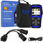
Service technicians have no problem recognising breakdowns and carrying out machine diagnostics, Error codes and their interpretation for Toyota Camry cars from 2006 release, plus they are familiar with equipment from a variety of manufacturers.
 The Toyota Camry is an automobile sold internationally by the Japanese manufacturer Toyota since 1982, spanning multiple generations. Originally compact in size (narrow-body), later Camry models have grown to fit the mid-size classification (wide-body)—although the two sizes co-existed in the 1990s. Since the release of the wide-bodied versions, Camry has been extolled by Toyota as the firm’s second “world car” after the Corolla. In Japan, Camry was once exclusive to Toyota Corolla Store retail dealerships. Narrow-body cars also spawned a rebadged sibling in Japan, the Toyota Vista —also introduced in 1982 and sold at Toyota Vista Store locations. Diesel fuel versions have previously retailed at Toyota Diesel Store.
| P0010 | Camshaft Position Sensor A Circuit (Row 1) | 1. Open or short in valve circuit oil supply to oil cooler ( OCV )
2. OCV 3. Electronic engine control unit (Electronic control unit) |
| P0010 | Position of a camshaft And – gazoras overrun or system performance (Row 1) | 1. Gas distribution phases
2. OCV 3. OCV filter 4. Cog wheel 5. Electronic control unit |
| P 0012 | Camshaft position a – gazoras delays with excessive delay (row 1) | The same as for P 0011 |
| P0016 | The relationship between the positions of the crankshaft and camshaft (sensor A, row 1) | 1. Mechanical system (leaping or growing timing chain)
2. Electronic block of management |
| P0031 | Weak current in the control circuit of the oxygen sensor heater ( A / F) (row 1 sensor 1) | 1. Open in the air-to-fuel ratio ( A / F ) sensor heater circuit
2. Heater sensor A / F (sensor 1) 3. Engine compartment distribution unit (electronic fuel injection system ( EFI ) relay ) 4. Electronic block of management |
| P0032 | Strong current in the control circuit of the oxygen sensor heater ( A / F ) (row 1 sensor 1) | 1. A / E Sensor Heater Circuit Short
2. A / E Sensor Heater (Sensor 1) 3. Engine compartment distribution unit ( EFIrelay ) 4. Electronic block of management |
| P0037 | Weak current in the control circuit of the oxygen sensor heater (sensor 1 row 2) | 1. Break in oxygen sensor heater target ( HO 2)
2. Heater HO sensor 2 (sensor 2) 3. Engine compartment distribution unit ( EFI relay ) 4. Electronic block of management |
| P0038 | Strong current in the control circuit of the oxygen sensor heater (sensor 2 row one) | 1. Short circuit in the oxygen sensor heater circuit (HO 2)
2. Heater HO sensor 2 (sensor 2) 3. Engine compartment distribution unit ( EFI relay ) 4. Electronic block of management |
| Code | Malfunction | Faulty plot |
| P0100 | Circuit sensor mass or volume air flow | 1. Open or short in the air flow sensor ( MAF )circuit
2. Sensor mass expense of air 3. Electronic block of management |
| P0102 | Low level signal at the input circuit of the sensor mass or volume air flow | 1. Open or short in air flow sensor circuit
2. Sensor mass expense of air 3. Electronic block of management |
| P0103 | High level signal at the input circuit of the sensor mass or volume air flow | 1. Open or short in air flow sensor circuit
2. Sensor mass expense of air 3. Electronic block of management |
| P0110 | Malfunction in the intake air temperature sensor circuit | 1. Open or short in the intake air temperature sensor circuit ( IAT )
2. Sensor I AT (built into the mass air flow sensor ( MAF ) 3. Electronic block of management |
| P0112 | Low level signal on the inlet air intake sensor circuit | 1. Short circuit in the IAT sensor circuit
2. IAT sensor (built-in 8 mass air flow sensor) 3. Electronic block of management |
| P0113 | High level of the input signal of the inlet air temperature sensor circuit | 1. Open circuit IAT sensor
2. IAT sensor (built into mass air flow sensor) 3. Electronic block of management |
| P0115 | Malfunction in the coolant temperature sensor circuit fluid | 1. Open or short in the coolant temperature sensor (ECT) target
2. ECT Sensor 3. Electronic block of management |
| P0116 | Malfunction in the coolant temperature sensor circuit liquid, due to the output of its characteristics beyond the permissible range / true value of the parameter | 1. Thermostat
2. ECT Sensor |
| P0117 | Low level signal on the input of the sensor target coolant temperature | 1. Short circuit in the ECT sensor circuit
2. ECT sensor 3. Electronic block of management |
| P0118 | High level signal at the sensor circuit input by that coolant temperature | 1. Open circuit ECT sensor
2. ECT Sensor 3. Electronic block of management |
| P0120 | Sensor / Switch Circuit Malfunction -A- Polo throttle / pedal | 1. Throttle Position Sensor ( TP ) (built into the throttle body)
2. Electronic block of management |
| P0121 | Throttle / Pedal Position Sensor / Switch A Circuit Malfunction Related to Range / Characteristics | TP sensor (built into body / throttle) |
| P0122 | Low level signal at the input of the sensor circuit polo throttle pedal A | 1. TP sensor (built into the throttle body) short circuit in the VTA 1 circuit
2. Broken in VC circuit 3. Electronic block of management |
| P0123 | The high level of the signal at the input of the sensor circuit Pedal / Throttle A Positions | 1. TP sensor (built into the throttle body)
2. Breakage in a chain VTA1 3. Breakage in a chain E2 4. Short circuit between VC and VTA 1 targets 5. Electronic block of management |
| P0136 | Malfunction in the oxygen sensor circuit (sensor 2 rows 1) | 1. Open or short in HO 2 sensor circuit ;(sensor 2)
2. HO 2 sensor ; ( sensor 2) 3. Heater HO 2 sensor ; ( sensor 2) 4. Air-to-fuel ( A / F ) ratio sensor (sensor 1) 5. Engine compartment distribution unit ( EFIrelay ) 6. Gas leakage from exhaust system |
| P0137 | Low voltage in the oxygen sensor circuit (Row 1, Sensor 2) | 1. HO 2 sensor circuit open (sensor 2)
2. Sensor BUT; ( sensor 2) 3. Heater BUT sensor ; ( sensor 2) 4. Engine compartment distribution unit ( EFIrelay ) 5. Exhaust gas exhaust system |
| P0138 | Oxygen Sensor Circuit High Voltage (Sensor 2, Row 1) | 1. Short circuit in the HO 2 sensor circuit(Sensor 2)
2. HO 2 sensor (sensor 2) 3. Internal circuit malfunction Electronic control unit |
| P0171 | Excessive impoverishment of the mixture in the system (row 1) | 1. System fence of air
2. Nozzle littered 3. Sensor mass expense of air 4. ECT Sensor 5. The pressure in the fuel system 6. Exhaust gas leaks from exhaust system 7. Open or short in A / F sensor circuit (Sensor 1) 8. Sensor A / F (sensor 1) 9. A / F sensor heater (yes chic 1) 10. Engine compartment distribution unit ( EFIrelay ) 11. A / F Sensor Heater Circuit and EFI Relay 12. Connections hose ventilation crankcase 13. Hose and papin crankcase ventilation 14. Electronic block of management |
| P0172 | Excessive enrichment of the mixture in the system (row 1) | 1. A leak through nozzle or blockage
2. Sensor mass expense of air 3. ECT Sensor 4. System ignition 5. The pressure in the fuel system 6. Gas leakage from exhaust system. 7. Breakage or a short closure at chains sensor A / F (sensor 1) 8. Sensor A / F (sensor 1) 9. Heater sensor A / F (sensor 1) 10. Engine compartment distribution unit ( EFI relay) 11. A / F sensor heater and EFI relay targets 12. Electronic block of management |
| P0220 | Pedal / Throttle Position Sensor Circuit | 1. TP sensor (built into the throttle body) |
| P0222 | Low level at the input of the pedal / throttle position sensor circuit “B” | 1. TP sensor (built into the throttle body)
2. A short short circuit in the VTA2 circuit 3. Broken in VC circuit 4. Electronic block of management |
| P0223 | Pedal / Throttle Position Sensor B Circuit High Input | 1. TP sensor built into throttle body
2. Breakage in a chain VIA2 3. Breakage in a chain E2 4. Short circuit between VC and VIA 2 circuits |
| P0300 | Irregular / Multiple Ignition Detection in Cylinder | 1. Open or short in engine wiring harness
2. Connection connector 3. Connections vacuum hose 3. System ignition 5. Injector 6. The pressure in the fuel system 7. Sensor mass expense of air 8. ECT Sensor 9. Pressure compression 10. The gap in the drive valves 11. Phases gas distribution 12. Hose and valve ventilation crankcase 13. Compound hose ventilation crankcase 14. System fence of air
|
| P0301 | Ignition registration registration in cylinder 1 | Same as for P 0300 |
| P0302 | Misfire detection in cylinder 2 | Same as for P 0300 |
| P0303 | Exposure of residence permit in cylinder 3 | Same as for P 0300 |
| P0304 | Misfire detection in cylinder 4 | Same as for P 0300 |
| P0327 | Low level signal at the input of the knock sensor circuit 1 (row 1 or a separate sensor) | 1. short closure at goals sensor detonation and
2. Sensor detonation 3. Electronic block of management |
| P0328 | high signal level at the input of the knock sensor circuit 1 (row 1 or a separate sensor) | 1. breakage at goals sensor detonation and
2. Sensor detonation 3. Electronic block of management |
| P0335 | Crankshaft Position Sensor A Circuit | 1. Open or short in crankshaft position sensor (CKP) circuit
2. Sensor TFR 3. Plate sensor TFR 4. Electronic block of management |
| P0339 | Intermittent Crankshaft Position Sensor A Signal | Same as for P 0335 |
| P0340 | Camshaft Position Sensor Circuit “A * (Row 1 or Separate Sensor) | 1. Open or short in the distribution position sensor (CMP) circuit
2. CMP sensor 3. Distributive shaft 4. Jump chain the drive gas distribution bodymechanism 5. Electronic block of management |
| P0351 | Ignition coil low / high voltage circuit A | 1. System ignition
2. Open or short in IGF 1 and IGT between the ignition coils (1-4) and the Electronic control unit 3. Coils Ignition No. 1 – 4 4. Electronic block of management |
| P0352 | Ignition coil low / high voltage circuit V | Same as for P 0351 |
| P0353 | Ignition coil low / high voltage circuit C | Same as for P 0351 |
| P0354 | Ignition coil low / high voltage circuit Niya D | Same as for P 0351 |
| P0420 | Efficiency of the catalytic neutralization system below the threshold level (row 1) | 1. Reception room pipe (with TWC)
2. Exhaust gas leaks from exhaust system 3. Air-to-fuel ( A / F ) ratio sensor (sensor I ) 4. Heated Oxygen Sensor (H O 2) (Date 2) |
| P0443 | Circuit control valve purge system caught fuel vapor | 1. open or short in purge vacuum valve circuit
2. Electrovacuum valve purge 3. Electronic block of management |
| P0500 | Vehicle Speed Sensor Malfunction | 1. Open or short in speed signal circuit
2. Shield appliances 3. Electronic block of management systemsanti-skid 4. Sensor speeds the car 5. Electronic block of management |
| P0504 | A / V Brake Switch Signal Correlation | 1. Short circuit in the signal circuit of the brake light switch
2. Switch table signals 3. Fuse STOP 4. IGN fuse 5. Electronic block of management |
| P0505 | Malfunction of the idle speed control system | 1. ECTS (electronic throttle control system Noah valve)
2. System fence of air 3. Compound hose ventilation crankcase 4. Electronic block of management |
| P0560 | Invalid system voltage | 1. Open circuit in the auxiliary power supply
2. Rechargeable battery 3. findings rechargeable batteries 4. Fuse FFI №1 5. Electronic block of management |
| P0604 | Internal error operatively memory (RAM) control unit | Electronic block of management |
| P0606 | Processor Electronic Control Unit / PCM | Electronic block of management |
| P0607 | Workers specifications block of management | Electronic block of management |
| P0617 | High level signal in the starter relay circuit | 1. Parking / Neutral Position Sensor ( PNP ) (for models with automatic transmission)
2. Clutch release switch (for models with manual transmission) 3. Chain relay starter 4. Ignition lock b. Electronic control unit |
| P0657 | Actuator power supply circuit / open circuit | Electronic block of management |
| P0724 | High level signal in the circuit of the brake switch B | 1. Short circuit in the signal circuit of the brake light switch
2. Switch brake lights 3. Electronic block of management |
| P2102 | Weak current in the motor circuit of the throttle actuator | 1. Open circuit in the throttle actuator circuit
2. Drive unit throttle dampers 3. Electronic block of management |
| P2103 | Strong current in the motor circuit of the throttle actuator | 1. Short circuit in the throttle actuator circuit
2. Drive unit throttle dampers 3. Throttle damper 4. Housing throttle valve assembly 5. Electronic block of management |
| P2 111 | Throttle Control System – Jadeopen position | 1. Drive unit throttle dampers
2. Housing throttle valve assembly 3. Throttle damper |
| P2112 | Throttle Control System – Jadeclosed position | Same as for P 2111 |
| P2118 | Throttle actuator motor current out of range / invalid mode | 1. Open circuit FTCS power supply
2. Rechargeable battery 3. findings rechargeable batteries 4. ETCS fuse 5. Electronic block of management |


 JCB Fault Codes List
 Fault Codes and diagnostic code Information for Caterpillar Control
 MAN TGA Fault codes list