Service technicians have no problem recognising breakdowns and carrying out machine diagnostics, Shaanxi Trucks Fault Codes, plus they are familiar with equipment from a variety of manufacturers.
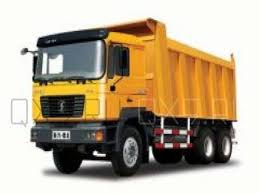 Shaanxi Automobile Group is one of the biggest truck manufacturers in China. It is based in Xi’an, Shaanxi province, China. It employs more than 13,000 employees. It manufactures heavy duty truck, buses (chassis), medium-size heavy truck and heavy duty axles for trucks. It’s bus chassis business is organized under the Eurostar Bus brand. SHAANXI D’LONG is a new type of heavy commercial vehicle. Designed and manufactured by SHAANXI in accordance with modern market requirements, it represents manufacturing techniques of MAN, Germany. Technical specifications include the MAN F2000 cab, a 7.5-ton front loading shaft, a WeiFang diesel engine, and an improved STYRE drive axle. In addition, this truck is today included in the elite of its class in terms of comfort and external characteristics.
| No. | Description of malfunction | Flash code |
| 1 | Voltage error in the intake air meter | 2 3 4 |
| 2 | Positive intake air flow meter above maximum threshold | 2 3 4 |
| 3 | The positive coefficient of the intake air flow meter is above the maximum threshold value (at idle) or below the minimum threshold | 2 3 4 |
| 4 | Positive coefficient of the intake air flow meter idling above the maximum threshold value or below the minimum threshold value | 2 3 4 |
| 5 | Positive intake air flow meter coefficient above or below the maximum threshold minimum threshold | 2 3 4 |
| 6 | Intake air flow sensor moved above maximum threshold | 2 3 4 |
| 7 | Intake air flow sensor moved below minimum threshold | 2 3 4 |
| 8 | Flowmeter Sensor Hardware Error | 2 3 4 |
| 9 | Intake Air Meter Source Signal Exceeds Maximum Threshold | 2 3 4 |
| 10 | Airflow source signal below minimum threshold | 2 3 4 |
| 11 | A / C compressor runs without load | 3 1 3 |
| 12 | Air conditioner compressor overheating | 3 1 3 |
| 13 | Open circuit when disconnecting A / C compressor load | 3 1 3 |
| 14 | Overheating of the compressor air conditioner when the load is disconnected | 3 1 3 |
| 15 | Short circuit of the power source when disconnecting the load of the air conditioning compressor | 3 1 3 |
| 16 | A / C compressor ground fault when disconnecting the load | 3 1 3 |
| 17 | Short circuit of the power source when the air conditioner compressor is operating | 3 1 3 |
| 18 | Short circuit of the earth at work of the compressor of the conditioner | 3 1 3 |
| 19 | Air conditioner switch CAN bus input failure | 3 1 4 |
| 20 | Air conditioning switch CAN input bus timeout | 3 1 4 |
| 21 | Direct deviation of the air regeneration controller exceeds the upper threshold value | 2 8 1 |
| 22 | Negative deviation of the air regeneration controller exceeds the upper trading value | 2 8 1 |
| 23 | Direct deviation of the air controller exceeds the upper threshold value | 2 8 1 |
| 24 | Negative deviation of the air controller exceeds the upper threshold value | 2 8 1 |
| 25 | Rgn time exceeded to air controller Nrm mode | 2 8 1 |
| 26 | High voltage signal off the intake air heating grid | 3 2 3 |
| 27 | Low voltage signal when the intake air heating grid is off | 3 2 3 |
| 28 | High voltage signal when the intake air heating grid is on | 3 2 3 |
| 29 | Low voltage signal when the intake air heating grid is on | 3 2 3 |
| 30 | The intake air heating coil is constantly on | 3 2 2 |
| 31 | Incorrect cold start signal at temperature_0 | 4 8 1 |
| 32 | Incorrect cold start signal at temperature_1 | 4 8 1 |
| 33 | Incorrect cold start signal at temperature_2 | 4 8 1 |
| 34 | Incorrect cold start signal at temperature_3 | 4 8 1 |
| 35 | Incorrect cold start signal at temperature_4 | 4 8 1 |
| 36 | Incorrect cold start signal multiple temperature | 4 8 1 |
| 37 | Actuator_0 power supply short circuit | 1 1 4 |
| 38 | Actuator_1 power supply short circuit | 1 1 5 |
| 39 | Actuator_2 power supply short circuit | 1 1 6 |
| 40 | Actuator_0 earth fault | 1 1 4 |
| 41 | Actuator_1 earth fault | 1 1 5 |
| 42 | Actuator_2 earth fault | 1 1 6 |
| 43 | Battery voltage too high | 1 2 4 |
| 44 | Low battery voltage | 1 2 4 |
| 45 | Battery voltage signal too high | 1 2 4 |
| 46 | Battery voltage signal too low | 1 2 4 |
| 47 | Signals of the main and auxiliary brakes do not match | 2 2 3 |
| 48 | Brake signal error | 2 2 3 |
| 49 | Error of the main wire A CAN bus | 4 1 1 |
| 50 | Main wire error in CAN bus | 4 1 2 |
| 51 | Main wire error With CAN bus | 0 0 0 |
| 52 | Error of the main wire D CAN bus | 0 0 0 |
| 53 | Error off main wire A CAN bus | 4 1 1 |
| 54 | Error off main wire in CAN bus | 4 1 2 |
| 55 | Error of the switched off main wire With CAN bus | 0 0 0 |
| 56 | Error off main wire D CAN bus | 0 0 0 |
| 57 | Wrong static engine coolant temperature signal | 2 4 2 |
| 58 | Incorrect dynamic coolant temperature signal | 2 4 2 |
| 59 | Engine coolant temperature error, coming from CAN bus signal | 2 4 1 |
| 60 | The voltage of the initial engine coolant temperature signal exceeds the upper threshold value | 2 4 1 |
| 61 | The voltage of the initial signal of the engine coolant temperature of the lower minimum threshold value | 2 4 1 |
| 62 | Incorrect coolant temperature signal (Temperature and selected second temperature deviation above maximum threshold value). | 2 4 2 |
| 63 | Clutch signal is incorrect (Transmission has changed, but clutch signal has not changed) | 2 2 2 |
| 64 | Clutch signal error coming from CAN bus | 2 2 2 |
| 65 | Exceeding Turbine Protection Torque Limit | 5 2 1 |
| 66 | Exceeding motor protection torque limit | 5 2 2 |
| 67 | Exceeding injection torque protection limit | 5 2 3 |
| 68 | Exceeding the torque limit exceeding reports | 5 2 4 |
| 69 | Exceeding torque limit by mountain brake | 5 3 4 |
| 70 | Particulate Filter Torque Limit Exceeded | 5 3 3 |
| 71 | Exceeding torque limit by torque limiter | 5 3 2 |
| 72 | Exceeding torque limit by smoke limit | 5 3 1 |
| 73 | Error in waiting time for sending information from CAN bus to ASK | 0 0 0 |
| 74 | Error waiting time to send information from the CAN bus to A mbcon | 4 1 3 |
| 75 | Error of data length AT 1 IG 1 received by CAN | 4 2 2 |
| 76 | Timeout error for receiving CAN data bus AT 1 IG | 4 2 2 |
| 77 | Error waiting for CAN to receive data bus AT 1 IGC 1 | 4 2 2 |
| 78 | Error waiting for CAN to receive data bus AT 1 IGC 2 | 4 2 2 |
| 79 | Error in data length AT 1 O 1 received by CAN | 4 2 1 |
| 80 | Error timeout for receiving CAN data bus AT 1 O 1 | 4 2 1 |
| 81 | Latency Error With AN Information AT 1 OGC 1 NOx Sensor | 4 2 1 |
| 82 | Latency Error With AN Information AT 1 OGC 2 NOx Sensor | 4 2 1 |
| 83 | Communication error between ECU and NOx sensor | 0 0 0 |
| 84 | The expiration of YOU in the first digital storage | 0 0 0 |
| 85 | Digital storage timeout from digital storage | 0 0 0 |
| 86 | Communication error between ECU and NOx sensor | 0 0 0 |
| 87 | The expiration of YOU in the first digital storage | 0 0 0 |
| 88 | Digital storage timeout from digital storage | 0 0 0 |
| 89 | The expiration of YOU in the first digital storage | 0 0 0 |
| 90 | Digital storage timeout from digital storage | 0 0 0 |
| 91 | Error SPN1 DCU Information | 4 2 3 |
| 92 | DCU Information SPN2 Error | 4 2 3 |
| 93 | Error SPN3 DCU Information | 4 2 3 |
| 94 | Error SPN4 DCU Information | 4 2 3 |
| 95 | Error SPN5 DCU Information | 4 2 3 |
| 96 | DCU BAM timeout | 4 2 4 |
| 97 | SAE validation error | 0 0 0 |
| 98 | Error waiting time to receive CAN information EBC 1 | 0 0 0 |
| 99 | Error waiting for CAN information EEC 1 | 4 1 3 |
| 100 | Error waiting for CAN information EEC 2 | 0 0 0 |
| 101 | Error waiting for CAN information EEC 3 | 0 0 0 |
| 102 | Error timeout EFL _ P 1 sent by CAN | 0 0 0 |
| 103 | CAN Stop Engine Request Error | 0 0 0 |
| 104 | EngTemp timeout error sent by CAN | 4 1 3 |
| 105 | ERC 1 timeout error sent by CAN | 0 0 0 |
| 106 | CAN ETC 1 timeout error | 4 2 5 |
| 107 | CAN ETC 2 timeout error | 4 2 5 |
| 108 | Error timeout FLECO, sent by CAN | 0 0 0 |
| 109 | CAN timeout error sent by CAN | 4 1 3 |
| 110 | Error information CAN sensor NOx | 4 2 1 |
| 111 | Error information CAN sensor NOx | 4 2 2 |
| 112 | Error information CAN sensor NOx | 4 2 1 |
| 113 | Error information CAN sensor NOx | 4 2 2 |
| 114 | Error information CAN sensor NOx | 4 2 1 |
| 115 | Error information CAN sensor NOx | 4 2 2 |
| 116 | Error information CAN sensor NOx | 4 2 1 |
| 117 | Error information CAN sensor NOx | 4 2 2 |
| 118 | Error information CAN sensor NOx | 4 2 1 |
| 119 | Error information CAN sensor NOx | 4 2 2 |
| 120 | Error information CAN sensor NOx | 4 2 1 |
| 121 | Error information CAN sensor NOx | 4 2 2 |
| 122 | Error information CAN sensor NOx | 4 2 1 |
| 123 | Error information CAN sensor NOx | 4 2 2 |
| 124 | Error information CAN sensor NOx | 4 2 1 |
| 125 | Error information CAN sensor NOx | 4 2 2 |
| 126 | BAM low level waiting time DM 19 error | 4 2 1 |
| 127 | BAM Top Level DM 19 Latency Error | 4 2 2 |
| 128 | Error SAE J 1939 Nox Oxygen Concentration Sensor CAN Information | 4 2 1 |
| 129 | Error SAE J 1939 Nox Oxygen Concentration Sensor CAN Information | 4 2 2 |
| 130 | CAN ETC 1 timeout error | 0 0 0 |
| 131 | DFC SAE J1939 Error | 4 2 1 |
| 132 | Error information CAN sensor NOx | 4 2 2 |
| 133 | Error information CAN sensor oxygen concentration Nox | 4 2 1 |
| 134 | Error information CAN sensor oxygen concentration Nox | 4 2 2 |
| 135 | Information error CAN power supply oxygen concentration sensor Nox | 4 2 1 |
| 136 | Information error CAN power supply oxygen concentration sensor Nox | 4 2 2 |
| 137 | Information error CAN Nox oxygen sensor temperature | 4 2 1 |
| 138 | Information error CAN Nox oxygen sensor temperature | 4 2 2 |
| 139 | CAN shutdown information timeout error | 0 0 0 |
| 140 | CAN Timeout Error TCO 1 | 0 0 0 |
| 141 | CAN Timeout Error TI 1 | 0 0 0 |
| 142 | Error timeout timedate, received CAN | 0 0 0 |
| 143 | Active timeout CANTSC 1 AE | 4 1 4 |
| 144 | Passive Information Timeout CANTSC 1 AE | 4 1 4 |
| 145 | Active timeout CANTSC 1 AR | 4 1 4 |
| 146 | Passive Information Timeout CANTSC 1 AR | 4 1 4 |
| 147 | Passive Information Timeout CANTSC 1 DE | 4 1 5 |
| 148 | Passive Information Timeout CANTSC 1 DE | 4 1 5 |
| 149 | Passive Information Timeout CANTSC 1 DR | 4 1 5 |
| 150 | Passive Information Timeout CANTSC 1 DR | 4 1 5 |
| 151 | Active Information Waiting Time CANTSC 1 PE | 4 1 6 |
| 152 | Passive Information Timeout CANTSC 1 PE | 4 1 6 |
| 153 | Active timeout CANTSC 1 VE | 4 1 7 |
| 154 | Passive Information Timeout CANTSC 1 VE | 4 1 7 |
| 155 | Active timeout CANTSC 1 TR | 4 1 7 |
| 156 | Passive Information Timeout CANTSC 1 TR | 4 1 7 |
| 157 | Active timeout CANTSC 1 VE | 4 1 8 |
| 158 | Passive Information Timeout CANTSC 1 VE | 4 1 8 |
| 159 | Active Information Expiration CANTSC 1 VR | 4 1 8 |
| 160 | Passive Timeout CANTSC 1 VR | 4 1 8 |
| 161 | Error timeout TSC 1 the AE, obtained CAN | 4 1 4 |
| 162 | Error timeout TSC 1 the AR, received CAN | 4 1 4 |
| 163 | Error timeout TSC 1 DE, received CAN | 4 1 5 |
| 164 | CAN Timeout Error TSC 1 DR Received by CAN | 4 1 5 |
| 165 | Error timeout TSC 1, the PE, received CAN | 4 1 6 |
| 166 | Error timeout TSC 1 the TE, obtained CAN | 4 1 7 |
| 167 | Error timeout TSC 1 TR, received CAN | 4 1 7 |
| 168 | Error timeout TSC 1 TR, received CAN | 4 1 8 |
| 169 | CAN Timeout Error TSC 1 VR Received by CAN | 4 1 8 |
| 170 | CAN Timeout Error | 0 0 0 |
| 171 | Information error CAN Nox oxygen sensor temperature | 0 0 0 |
| 172 | Timeout CAN information TxPGNRQ | 0 0 0 |
| 173 | UAA 1 timeout error sent by CAN | 0 0 0 |
| 174 | UAA 2 timeout error sent by CAN | 0 0 0 |
| 175 | UAA 3 timeout error sent by CAN | 0 0 0 |
| 176 | UAA 4 timeout error sent by CAN | 0 0 0 |
| 177 | UAA 5 timeout error sent by CAN | 0 0 0 |
| 178 | UAA 6 timeout error sent by CAN | 0 0 0 |
| 179 | UAA 7 timeout error sent by CAN | 0 0 0 |
| 180 | UAA 8 timeout error sent by CAN | 0 0 0 |
| 181 | VD timeout error sent by CAN | 0 0 0 |
| 182 | VEP 1 timeout error sent by CAN | 0 0 0 |
| 183 | WFI timeout error sent by CAN | 0 0 0 |
| 184 | OBD Torque Limit Activation Error | 5 1 1 |
| 185 | Cruise Control Switch Error | 3 4 1 |
| 186 | Cy 146 error related to SPI and COM | 1 1 1 |
| 187 | Cy 320 bug related to SPI and COM | 1 1 1 |
| 188 | Battery voltage too high | 1 2 4 |
| 189 | Low battery voltage | 1 2 4 |
| 190 | Invalid Mountain Brake Signal | 3 4 2 |
| 191 | Invalid machine stop switch signal | 3 4 3 |
| 192 | Invalid machine start switch signal | 3 4 3 |
| 193 | Mountain brake in motion without load | 3 1 5 |
| 194 | Mountain brake overheating in motion | 3 1 5 |
| 195 | Mountain brake power source short circuit | 3 1 5 |
| 196 | Mountain brake ground fault | 3 1 5 |
| 197 | EEP Erase Error | 1 1 7 |
| 198 | Error reading EEP | 1 1 7 |
| 199 | EEP write error | 1 1 7 |
| 200 | EGR valve current limitation | 3 5 1 |
| 201 | EGR valve voltage signal in closed position not within operating limits | 3 5 2 |
| 202 | EGR valve voltage signal in open position not within operating limits | 3 5 2 |
| 203 | EGR valve voltage signal in closed position with training voltage not within operating limits | 3 5 2 |
| 204 | EGR valve control deviations during cold start not within operating limits | 3 5 3 |
| 205 | Positive deviation of EGR valve control at the time of a cold start is not within operating limits | 3 5 3 |
| 206 | Negative deviation of EGR valve control at the time of a cold start is not within operating limits | 3 5 3 |
| 207 | Clogged valve EGR in the closed position | 3 5 3 |
| 208 | Contamination valve EGR in the open position | 3 5 3 |
| 209 | The deviation of the time length of the EGR valve signals in the closed position at two training voltages is too large | 3 5 2 |
| 210 | The deviation of the time length of the EGR valve signals in the open position at two training voltages is too large | 3 5 2 |
| 211 | EGR valve without load | 3 5 4 |
| 212 | EGR valve overheating | 3 5 4 |
| 213 | EGR valve opening feedback above threshold | 3 5 5 |
| 214 | EGR valve opening feedback below threshold | 3 5 5 |
| 215 | EGR valve power supply short circuit | 3 5 4 |
| 216 | EGR valve ground short | 3 5 4 |
| 217 | The short time deviation of the EGR valve signals in the closed position at two training voltages is too large | 3 5 2 |
| 218 | The short-time deviation of the EGR valve signals in the open position at two training voltages is too large | 3 5 2 |
| 219 | EGR valve feedback voltage above threshold | 3 5 5 |
| 220 | EGR valve feedback voltage below threshold | 3 5 5 |
| 221 | EGR valve connection not reliable | 3 5 4 |
| 222 | Request to turn off the engine disables fuel injection | 5 1 2 |
| 223 | Engine overspeed | 5 1 3 |
| 224 | Activation of motor protection | 5 1 4 |
| 225 | Engine in motion gives no load | 3 4 4 |
| 226 | Engine temperature rises at rpm | 3 4 4 |
| 227 | Short circuit of the engine power source at operating speed | 3 4 4 |
| 228 | Short circuit of the earth of the engine on working turns | 3 4 4 |
| 229 | Ambient pressure CAN information error | 2 3 2 |
| 230 | Ambient pressure sensor voltage is above maximum limit | 2 3 2 |
| 231 | Ambient pressure sensor voltage below minimum limit | 2 3 2 |
| 232 | Invalid ambient temperature signal | 2 3 5 |
| 233 | Ambient temperature sensor voltage above maximum limit | 2 3 5 |
| 234 | Ambient temperature sensor voltage below minimum limit | 2 3 5 |
| 235 | Camshaft signal error | 1 2 3 |
| 236 | No camshaft signal | 1 2 3 |
| 237 | Camshaft signal deviation error | 1 2 3 |
| 238 | Crankshaft signal error | 1 2 2 |
| 239 | No crankshaft signal | 1 2 2 |
| 240 | No load on the mountain brake relay | 3 1 1 |
| 241 | Excessive temperature brake relay | 3 1 1 |
| 242 | Mountain brake relay power supply short circuit | 3 1 1 |
| 243 | Short circuit of the earth of the relay of a mountain brake | 3 1 1 |
| 244 | Invalid mountain brake relay position signal | 3 1 1 |
| 245 | Mountain brake relay position error | 3 1 1 |
| 246 | Too much deviation A / D conversion | 1 1 1 |
| 247 | Fan 1 solenoid valve no load | 3 1 2 |
| 248 | Fan 2 solenoid valve no load | 3 1 2 |
| 249 | Fan solenoid valve 1 temperature rise | 3 1 2 |
| 250 | Fan solenoid valve 2 overtemperature | 3 1 2 |
| 251 | Fan 1 solenoid valve power supply short circuit | 3 1 2 |
| 252 | Fan 2 solenoid valve power supply short circuit | 3 1 2 |
| 253 | Short circuit of the earth of the solenoid valve of the fan 1 | 3 1 2 |
| 254 | Short circuit of the earth of the electromagnetic valve of fan 2 | 3 1 2 |
| 255 | No load PWM fan drive | 3 1 2 |
| 256 | Overheating PWM Fan Drive | 3 1 2 |
| 257 | PWM fan power supply short circuit | 3 1 2 |
| 258 | PWM Fan Ground Short Circuit | 3 1 2 |
| 259 | Fan speed too long at rpm | 3 1 6 |
| 260 | Fan speeds at operating speeds exceed the maximum value | 3 1 6 |
| 261 | Fan revolutions at operating speeds below the minimum value | 3 1 6 |
| 262 | Error correction oil balance 1 | 4 8 2 |
| 263 | Error correction oil balance level 2 | 4 8 2 |
| 264 | Oil Level Balance Correction Error 3 | 4 8 2 |
| 265 | Oil Level Balance Correction Error 4 | 4 8 2 |
| 266 | Oil Level Balance Correction Error 5 | 4 8 2 |
| 267 | Oil Level Balance Correction Error 6 | 4 8 2 |
| 268 | Fuel differential pressure signal voltage above maximum value | 2 1 2 |
| 269 | Fuel differential pressure signal voltage above maximum value | 2 1 2 |
| 270 | Fuel filter clogging | 2 1 3 |
| 271 | Invalid fuel filter obstruction | 2 1 3 |
| 272 | No load on the fuel heating drive | 2 1 6 |
| 273 | Overheating of the fuel heating drive | 2 1 6 |
| 274 | Short circuit of the fuel heating drive power supply | 2 1 6 |
| 275 | Short circuit of the earth of the drive of heating of fuel | 2 1 6 |
| 276 | The voltage signal of the fuel water sensor is higher than the maximum value | 2 1 4 |
| 277 | The voltage signal of the fuel water sensor is higher than the maximum value | 2 1 4 |
| 278 | Too much water in the fuel | 2 1 1 |
| 279 | The fuel level in the fuel tank is below the minimum value, or the air in the hydraulic system | 2 1 7 |
| 280 | Fuel temperature sensor signal voltage above maximum value | 2 1 5 |
| 281 | Fuel temperature sensor signal voltage below minimum | 2 1 5 |
| 282 | Invalid fuel temperature signal | 2 1 5 |
| 283 | CAN signal error neutral | 2 2 7 |
| 284 | No load for intake air heater lamp | 3 3 2 |
| 285 | Overheated intake air heater lamp | 3 3 2 |
| 286 | Short circuit in the intake air heater lamp power supply | 3 3 2 |
| 287 | Short circuit of the ground of the intake air heater lamp | 3 3 2 |
| 288 | No intake air heating load | 3 2 1 |
| 289 | Intake Air Heater Overheat | 3 2 1 |
| 290 | Short circuit of the intake air heating power supply | 3 2 1 |
| 291 | Short circuit ground intake air heater | 3 2 1 |
| 292 | Injection frequency exceeds circuit limit | 0 0 0 |
| 293 | Injection frequency exceeds maximum fuel pump pressure limit | 0 0 0 |
| 294 | Injection frequency exceeds system limit | 0 0 0 |
| 295 | Injection frequency exceeds system limit | 0 0 0 |
| 296 | Unsuccessful engine start | 0 0 0 |
| 297 | Fuel rail pressure below minimum | 2 7 6 |
| 298 | Injector correction parameter 1 error | 4 8 3 |
| 299 | Injector correction parameter 2 error | 4 8 3 |
| 300 | Injector correction parameter 3 error | 4 8 3 |
| 301 | Injector correction parameter 4 error | 4 8 3 |
| 302 | Injector correction parameter 5 error | 4 8 3 |
| 303 | Injector correction parameter 6 error | 4 8 3 |
| 304 | Short circuit injection capacitor 1 | 1 5 1 |
| 305 | Short circuit injection capacitor 2 | 1 5 1 |
| 306 | Dedicated injection chip error | 1 5 3 |
| 307 | Open circuit injector 1 | 1 4 1 |
| 308 | Open circuit injector 2 | 1 4 2 |
| 309 | Open circuit injector 3 | 1 4 3 |
| 310 | Injector 4 open circuit | 1 4 4 |
| 311 | Injector 5 open circuit | 1 4 5 |
| 312 | Open circuit injector 6 | 1 4 6 |
| 313 | Injector 1 error (No definition, just saved) | 1 4 1 |
| 314 | Injector 2 error (No definition, just saved) | 1 4 2 |
| 315 | Injector Error 3 (No definition, just saved) | 1 4 3 |
| 316 | Injector Error 4 (No definition, just saved) | 1 4 4 |
| 317 | Injector Error 5 (No definition, just saved) | 1 4 5 |
| 318 | Injector Error 6 (No definition, just saved) | 1 4 6 |
| 319 | Injector 1 short circuit | 1 4 1 |
| 320 | Injector 2 short circuit | 1 4 2 |
| 321 | Injector 3 short circuit | 1 4 3 |
| 322 | Injector 4 short circuit | 1 4 4 |
| 323 | Injector 5 short circuit | 1 4 5 |
| 324 | Injector 6 short circuit | 1 4 6 |
| 325 | Short circuit of the lower or upper end of the nozzle 1 | 1 4 1 |
| 326 | Short circuit of the lower or upper end of the nozzle 2 | 1 4 2 |
| 327 | Short circuit of the lower or upper end of the nozzle 3 | 1 4 3 |
| 328 | Short circuit of the lower or upper end of the nozzle 4 | 1 4 4 |
| 329 | Short circuit of the lower or upper end of the nozzle 5 | 1 4 5 |
| 330 | Short circuit of the lower or upper end of the nozzle 6 | 1 4 6 |
| 331 | Voltage at PTO Switch Above Maximum Limit | 3 4 5 |
| 332 | Poor fuel level measurement module connection with ECU | 1 3 3 |
| 333 | Open circuit of the fuel level measuring module | 1 3 3 |
| 334 | Overheating of the fuel level measuring module | 1 3 3 |
| 335 | Short circuit of the power source of the upper end of the fuel level measuring module | 1 3 3 |
| 336 | Short circuit of the earth of the upper end of the module of measurement of level of fuel | 1 3 3 |
| 337 | Short circuit of the driver power source of the lower end of the fuel level measuring module | 1 3 3 |
| 338 | Short circuit of the ground of the driver of the lower end of the module for measuring the fuel level | 1 3 3 |
| 339 | The feedback signal voltage of the fuel level measuring module is above the maximum limit | 1 3 3 |
| 340 | The feedback signal voltage of the fuel level measuring module is below the minimum limit | 1 3 3 |
| 341 | MIL lamp without load | 3 3 1 |
| 342 | MIL lamp without load | 3 3 1 |
| 343 | MIL lamp without load | 3 3 1 |
| 344 | MIL lamp without load | 3 3 1 |
| 345 | PTO Switch Voltage Below Minimum Limit | 3 4 5 |
| 346 | Error converting digital-to-analog information | 2 6 2 |
| 347 | Error converting digital-to-analog information | 2 6 2 |
| 348 | Error conversion coefficient of digital-to-analog information | 2 6 2 |
| 349 | Communication error between the control module and the CPU | 2 6 2 |
| 350 | Communication error between the control module and the CPU | 2 6 2 |
| 351 | ECU RAM Error | 2 6 2 |
| 352 | Communication error between the control module and the CPU | 2 6 3 |
| 353 | Communication error between the control module and the CPU | 2 6 3 |
| 354 | Communication error between the control module and the CPU | 2 6 3 |
| 355 | Communication error between the control module and the CPU | 2 6 3 |
| 356 | Communication error between the control module and the CPU | 2 6 3 |
| 357 | Communication error between the control module and the CPU | 2 6 3 |
| 358 | Communication error between the control module and the CPU | 2 6 3 |
| 359 | Communication error between the control module and the CPU | 2 6 3 |
| 360 | Communication error between the control module and the CPU | 2 6 3 |
| 361 | Communication error between the control module and the CPU | 2 6 3 |
| 362 | Incompatible 2 accelerator pedal voltages | 2 6 4 |
| 363 | Invalid engine speed signal | 2 6 4 |
| 364 | Injector signal incorrect at power on | 2 6 4 |
| 365 | Invalid injection lead | 2 6 4 |
| 366 | Wrong fuel zero signal when power is turned on | 2 6 4 |
| 367 | Invalid efficiency signal after injection 2 | 2 6 4 |
| 368 | Close error 2 after injection | 2 6 4 |
| 369 | Invalid efficiency signal after injection 3 | 2 6 4 |
| 370 | With Overrun, the power-on time exceeds the maximum value. | 2 6 1 |
| 371 | Invalid injection volume correction signal | 2 6 4 |
| 372 | Ramp pressure error | 2 6 4 |
| 373 | Incompatible 2 long-distance accelerator pedal voltages | 2 6 4 |
| 374 | Incompatible real engine torque with permitted | 2 6 4 |
| 375 | The fuel rail pressure is limited by the function of the torque control unit | 2 6 4 |
| 376 | The air supply system is limited by the function of the torque control unit | 2 6 4 |
| 377 | The fuel injection level is limited by the function of the torque control unit. | 2 6 4 |
| 378 | The voltage of the power supply unit 1 exceeds the maximum value | 2 6 5 |
| 379 | The voltage of the power supply unit 1 is below the minimum value | 2 6 5 |
| 380 | Early activation of the main relay after switching on the ECU | 1 2 5 |
| 381 | Late activation of the main relay | 1 2 5 |
| 382 | Nox Sensor Power Supply Error Lower Position | 4 2 1 |
| 383 | Incorrect sensor signal compensation Nox low position low position | 4 2 1 |
| 384 | Incorrect sensor signal Nox lower position | 4 2 1 |
| 385 | NOx sensor lambda voltage above maximum value (low position) | 4 2 1 |
| 386 | NOx sensor lambda voltage below minimum value (low position) | 4 2 1 |
| 387 | NOx sensor lambda voltage above maximum value (low position) | 4 2 1 |
| 388 | NOx sensor lambda voltage below minimum value (low position) | 4 2 1 |
| 389 | NOx sensor lambda signal above maximum value (low position) | 4 2 1 |
| 390 | Nox sensor lambda signal voltage below minimum limit (low position) | 4 2 1 |
| 391 | Nox sensor lambda maximum deviation above maximum limit | 4 2 1 |
| 392 | The minimum deviation of the lambda signal of the Nox sensor is below the minimum limit (lower position) | 4 2 1 |
| 393 | The average deviation of the lambda signal of the Nox sensor is above the maximum limit (lower position) | 4 2 1 |
| 394 | The average deviation of the lambda signal of the Nox sensor is below the minimum limit (lower position) | 4 2 1 |
| 395 | Incorrect NOx signal of the Nox sensor (low position) | 4 2 1 |
| 396 | Incorrect status of the Nox signal of the Nox sensor (low position) | 4 2 1 |
| 397 | Nox Sensor Signal Above Maximum Limit (Low Position) | 4 2 1 |
| 398 | Nox Sensor Signal Below Minimum Limit (Low Position) | 4 2 1 |
| 399 | Nox Sensor Open Circuit (Lower Position) | 4 2 1 |
| 400 | Short circuit of a signal of the Nox sensor (lower position) | 4 2 1 |
| 401 | PTO switch voltage incorrect | 3 4 5 |
| 402 | Nox Sensor Power Error | 4 8 4 |
| 403 | Incorrect Nox Sensor Signal Compensation | 4 8 4 |
| 404 | Nox Sensor Signal Status Error | 4 8 4 |
| 405 | Nox Sensor Signal Status Error | 4 8 4 |
| 406 | Invalid high level Nox sensor signal | 4 8 4 |
| 407 | Lambda signal voltage of the upper level Nox sensor is above the maximum limit | 4 8 4 |
| 408 | High voltage Nox sensor lambda signal voltage below minimum limit | 4 8 4 |
| 409 | Lambda signal voltage of the upper level Nox sensor is above the maximum limit | 4 8 4 |
| 410 | High voltage Nox sensor lambda signal voltage below minimum limit | 4 8 4 |
| 411 | High Level Nox Sensor Lambda Signal Above Maximum Limit | 4 8 4 |
| 412 | High level Nox sensor lambda signal below minimum limit | 4 8 4 |
| 413 | The maximum deviation of the high level Nox sensor signal is above the maximum limit | 4 8 4 |
| 414 | Minimum deviation of the high level Nox sensor signal below the minimum limit | 4 8 4 |
| 415 | The average deviation of the high level Nox sensor signal is above the maximum limit | 4 8 4 |
| 416 | The average deviation of the high level Nox sensor signal is below the minimum limit | 4 8 4 |
| 417 | Invalid Nox High Level Nox Sensor Signal | 4 8 4 |
| 418 | Invalid high position Nox sensor position signal | 4 8 4 |
| 419 | Nox signal of the Nox sensor up position is above the maximum limit | 4 8 4 |
| 420 | Nox signal of the Nox sensor up position is below the minimum limit | 4 8 4 |
| 421 | Open circuit of the NOx signal of the Nox sensor up position | 4 8 4 |
| 422 | Short circuit of the NOx signal of the Nox sensor up position | 4 8 4 |
| 423 | Error deleting code from the repository | 4 8 5 |
| 439 | WDA activation error | 1 1 1 |
| 440 | Error low voltage WDA / ABE | 1 1 1 |
| 441 | WDA / ABE Voltage Test | 1 1 1 |
| 442 | Unknown WDA / ABE error | 1 1 1 |
| 443 | Oil Level Voltage Above Maximum Limit | 2 4 6 |
| 444 | Oil level voltage below minimum limit | 2 4 6 |
| 445 | Incorrect engine oil voltage signal | 2 4 6 |
| 446 | Oil Level Signal Above Maximum | 2 4 6 |
| 447 | The oil level signal is below the minimum value | 2 4 6 |
| 448 | Open circuit engine oil pressure indicator | 3 3 4 |
| 449 | Engine oil pressure indicator temperature is above normal | 3 3 4 |
| 450 | Short circuit in the engine oil pressure indicator power supply | 3 3 4 |
| 451 | Short circuit of the earth of the indicator of pressure of oil in the engine | 3 3 4 |
| 452 | Engine Oil Pressure Signal Error | 2 4 3 |
| 453 | Incorrect engine oil pressure signal | 2 4 3 |
| 454 | Engine oil pressure above maximum limit | 2 4 3 |
| 455 | Engine oil pressure below minimum limit | 2 4 3 |
| 456 | Error CAN signal engine oil pressure | 2 4 3 |
| 457 | Oil pressure signal voltage above maximum limit | 2 4 3 |
| 458 | Oil pressure signal voltage below minimum limit | 2 4 3 |
| 459 | Oil temperature signal above maximum limit | 2 4 4 |
| 460 | Error CAN signal engine oil temperature | 2 4 4 |
| 461 | Oil temperature signal voltage above maximum limit | 2 4 4 |
| 462 | Oil temperature signal voltage below minimum limit | 2 4 4 |
| 463 | Incorrect oil temperature signal | 2 4 4 |
| 464 | Positive turbine pressure deviation above maximum limit | 2 8 2 |
| 465 | Negative deviation of turbine pressure above maximum limit | 2 8 2 |
| 466 | Non-uniform change in oil level torque | 0 0 0 |
| 467 | Intake air pressure signal upper limit above maximum value | 2 3 1 |
| 468 | Intake air pressure signal upper limit below minimum value | 2 3 1 |
| 469 | Intake air pressure voltage signal above maximum limit | 2 3 1 |
| 470 | Intake air pressure voltage signal below minimum limit | 2 3 1 |
| 471 | POC particulate filter clogging | 4 7 1 |
| 472 | POC particulate filter removal | 4 7 2 |
| 473 | POC particulate filter differential pressure signal above maximum limit | 4 7 3 |
| 474 | POC particulate filter differential pressure signal below minimum limit | 4 7 3 |
| 475 | Particle Filter Voltage Differential Signal When AfterRun Above Maximum Limit | 4 7 3 |
| 476 | POCCAN particulate filter signal error | 4 7 3 |
| 477 | POC Particulate Filter Differential Voltage Signal Above Maximum Limit | 4 7 3 |
| 478 | POC particulate filter differential pressure voltage signal is below the minimum limit | 4 7 3 |
| 479 | Safety valve opening frequency has reached or exceeded the maximum value | 1 3 4 |
| 480 | Fuel rail pressure opens safety valve | 0 0 0 |
| 481 | Vibration in the fuel rail opened the safety valve | 0 0 0 |
| 482 | Safety valve opening | 1 3 5 |
| 483 | Fuel balance error at the time the safety valve opens | 1 3 6 |
| 484 | Medium ramp pressure exceeds acceptable limits | 1 3 6 |
| 485 | Safety valve opening time exceeded limit | 1 3 6 |
| 486 | Error of the power supply control unit inside the ECU | 1 1 1 |
| 487 | Direct deflection of the fuel rail control unit above the maximum value | 2 5 1 |
| 488 | The fuel level in the high pressure fuel pump is above the maximum limit, there is a fuel leak | 2 5 2 |
| 489 | Negative deviation of the small pump control unit in the fuel rail above the first limit | 2 5 5 |
| 490 | Negative deviation of the small pump control unit in the fuel rail above the first limit | 2 5 3 |
| 491 | Fuel rail pressure below minimum | 2 5 6 |
| 492 | Fuel rail pressure above first limit | 2 7 1 |
| 493 | Fuel rail pressure above second limit | 2 7 2 |
| 494 | In OverRun mode, the fuel level in the high-pressure fuel pump is higher than the maximum limit | 2 7 3 |
| 495 | At low idle, the set fuel level in the high-pressure fuel pump is higher than the minimum mark | 2 7 4 |
| 496 | Fuel rail pressure change exceeds maximum frequency limit | 2 7 5 |
| 497 | Direct pressure deviation in the fuel rail above the maximum value | 1 3 2 |
| 498 | Direct pressure deviation in the fuel rail below the minimum value | 1 3 2 |
| 499 | Fuel rail pressure exceeds maximum permissible limits | 1 3 6 |
| 500 | Fuel rail pressure sensor signal exceeds maximum limit | 1 3 1 |
| 501 | Fuel rail pressure signal voltage is below minimum | 1 3 1 |
| 502 | Error adjusting the level of urea in the injected fuel volume | 4 3 4 |
| 503 | SCR self-adaptation period exceeds the limit | 4 3 5 |
| 504 | SCR self-adaptation period below the set limit | 4 3 5 |
| 505 | Low average SCR conversion efficiency | 0 0 0 |
| 506 | The average actual SCR conversion efficiency is below level 1, exhaust exceeds 5 | 4 3 1 |
| 507 | The average actual SCR conversion efficiency is below level 2, exhaust exceeds 7 | 4 3 2 |
| 508 | Incorrect SCR Low Peak Nox Sensor Verification Signal | 4 2 1 |
| 509 | The difference between the signals of the sensors of the upper and lower levels of the Nox SCR sensor is higher than the maximum level | 4 2 1 |
| 510 | The difference between the signals of the sensors of the upper and lower levels of the Nox SCR sensor is below the minimum level | 4 2 1 |
| 511 | Invalid signal checking deviations of the sensor signal Nox lower level SCR | 4 2 1 |
| 512 | The difference between the signals of the sensors of the upper and lower levels of the Nox SCR sensor is higher than the maximum level | 4 2 2 |
| 513 | The difference between the signals of the sensors of the upper and lower levels of the Nox SCR sensor is below the minimum level | 4 2 2 |
| 514 | Urea does not enter the injected fuel | 4 3 6 |
| 515 | Urea level remaining insufficient | 4 3 8 |
| 516 | The residual urea level is below the warning level 1 | 4 3 8 |
| 517 | Urea residual level below warning level 2 | 4 3 8 |
| 518 | SCR ammonia storage control error | 4 3 7 |
| 519 | SCR Urea Return Pipeline Error | 4 4 1 |
| 520 | Urea injection pressure drop SCR | 4 4 1 |
| 521 | Urea injection pressure SCR | 4 4 1 |
| 522 | The temperature inside the ECU is above the maximum limit | 1 1 9 |
| 523 | Lack of SCR emptying at the end of the driving cycle | 4 4 7 |
| 524 | Urea injection overpressure in SCR urea level control unit | 4 4 2 |
| 525 | Urea injection pressure low in SCR urea level control unit | 4 4 3 |
| 526 | Urea injection overpressure after cooling the SCR urea pump | 4 4 2 |
| 527 | Urea Pressure Error SCR | 4 4 1 |
| 528 | SCR underpressure error | 4 4 1 |
| 529 | After lowering the pressure, the urea pressure in the SCR system is below the minimum limit | 4 4 1 |
| 530 | Urea tank overheating | 4 4 6 |
| 531 | Invalid ECU Indoor Unit Temperature | 1 1 9 |
| 532 | Invalid signal for exceeding the maximum temperature limit of the SCR sensor of the upper level | 4 4 4 |
| 533 | Invalid signal for exceeding the minimum temperature limit of the SCR sensor of the upper level | 4 4 4 |
| 534 | Invalid high temperature temperature sensor SCR | 4 4 4 |
| 535 | SCR Urea Nozzle Spray | 4 5 3 |
| 536 | SCR Urea Pump Check Valve Clogged | 4 5 3 |
| 537 | Urea consumption too high | 4 4 5 |
| 538 | Urea flow too small | 4 4 5 |
| 539 | SCR system PUQP function error | 4 4 1 |
| 540 | Incorrect heating of the SCR urea pump | 4 5 5 |
| 541 | Incorrect position of the SCR urea pump heating temperature sensor | 4 5 5 |
| 542 | Wrong urea pump heating temperature sensor signal during cold start | 4 5 5 |
| 543 | SCR Urea Temperature Sensor Incorrect | 4 5 6 |
| 544 | Incorrect SCR Urea Temperature Sensor Signal During Cold Start | 4 5 6 |
| 545 | Error urea tank temperature SCR | 4 4 6 |
| 546 | SCR restarts exceeded limit | 4 3 8 |
| 547 | PTO switch CAN message error | 3 4 5 |
| 548 | SCR urea pump heater turn-on duration in error range | 4 5 5 |
| 549 | Invalid range for SCR urea pump heater | 4 5 5 |
| 550 | SCR Pump Urea Temperature Measurement Module Failure | 4 5 4 |
| 551 | Accepted SCR urea pump PWM cycle is in the unacceptable range | 4 5 4 |
| 552 | Sine Error PWM Urea Pump | 4 5 4 |
| 553 | The duration of the inclusion of the temperature of the urea pump SCR in the wrong range | 4 5 6 |
| 554 | Invalid SCR urea pump temperature on duration | 4 5 6 |
| 555 | Pedal 1 voltage above maximum limit | 2 2 1 |
| 556 | Pedal 2 voltage above maximum limit | 2 2 1 |
| 557 | Pedal 1 long stroke voltage above maximum limit | 2 2 9 |
| 558 | Pedal 2 long stroke voltage above maximum limit | 2 2 9 |
| 559 | Pedal 1 voltage below minimum limit | 2 2 1 |
| 560 | Pedal 2 voltage below minimum limit | 2 2 1 |
| 561 | Pedal 1 long stroke voltage below minimum limit | 2 2 9 |
| 562 | Pedal 2 long stroke voltage below minimum limit | 2 2 9 |
| 563 | Urea level sensor voltage above maximum value | 4 4 5 |
| 564 | Urea level sensor voltage below minimum | 4 4 5 |
| 565 | Sensor 1 Power Supply Error | 1 1 2 |
| 566 | Sensor 2 Power Supply Error | 1 1 2 |
| 567 | Sensor 3 Power Supply Error | 1 1 2 |
| 568 | 12V sensor power too high | 1 1 3 |
| 569 | 12V sensor power too low | 1 1 3 |
| 570 | Too high power supply of the internal part of the sensor 12 V | 1 1 3 |
| 571 | Too low power supply inside the 12 V sensor | 1 1 3 |
| 572 | Parking calculation timer accuracy error | 1 1 1 |
| 573 | No load indicator of a stop of the car | 3 3 5 |
| 574 | Exceeding the temperature of the machine stop indicator | 3 3 5 |
| 575 | Short circuit of the machine stop indicator power supply | 3 3 5 |
| 576 | Short circuit of the earth of the indicator of a stop of the car | 3 3 5 |
| 577 | No starter load | 1 2 1 |
| 578 | Starter starting temperature rise | 1 2 1 |
| 579 | Starter relay power supply short circuit | 1 2 1 |
| 580 | Starter relay short circuit | 1 2 1 |
| 581 | No load when starting diagnostic indicators | 3 3 3 |
| 582 | Exceeding start temperature of diagnostic indicators | 3 3 3 |
| 583 | Diagnostic Indicator Power Supply Shorted | 3 3 3 |
| 584 | Earth fault diagnostic indicator | 3 3 3 |
| 585 | Reset 0 fault diagnosis program | 1 1 8 |
| 586 | Reset 1 fault diagnosis program | 1 1 8 |
| 587 | Reset 2 fault diagnosis program | 1 1 8 |
| 588 | Too big difference between pedal 1 and pedal 2 voltage signals | 2 2 1 |
| 589 | Invalid voltage signal between pedal 1, pedal 2 and idle switch | 2 2 1 |
| 590 | Too much difference between the voltage signals of the long pedal 1 and the long pedal 2 | 2 2 9 |
| 591 | T50 switch error | 3 4 5 |
| 592 | The signal temperature of the air temperature sensor is above the maximum limit | 2 3 4 |
| 593 | Air temperature sensor signal frequency below minimum limit | 2 3 4 |
| 594 | Air temperature sensor time signal above maximum value | 2 3 4 |
| 595 | Air temperature sensor time signal below minimum | 2 3 4 |
| 596 | CAN communication error of the intake air temperature signal after cooling | 2 3 3 |
| 597 | Intake air temperature sensor voltage signal after cooling above maximum limit | 2 3 3 |
| 598 | Intake air temperature sensor voltage signal after cooling below minimum limit | 2 3 3 |
| 599 | Incorrect intake air temperature after cooling | 2 3 3 |
| 600 | Internal ECU Temperature Sensor Voltage Signal Above Maximum Limit | 1 1 9 |
| 601 | The voltage signal of the internal temperature sensor of the ECU is below the minimum limit | 1 1 9 |
| 602 | Activation of choke valve electric current limitation | 3 6 1 |
| 603 | Air damper valve voltage in closed position is above maximum limit | 3 6 2 |
| 604 | Choke valve voltage in open position is above maximum limit | 3 6 2 |
| 605 | The voltage difference of the air damper valve exceeds the permissible limits. | 3 6 2 |
| 606 | Air Start Valve Cold Start Error | 3 6 3 |
| 607 | Direct deflection of the air damper exceeds the maximum value | 3 6 3 |
| 608 | Direct deflection of the air damper exceeds the minimum value | 3 6 3 |
| 609 | Choke valve clogging | 3 6 3 |
| 610 | Choke valve clogging | 3 6 3 |
| 611 | The choke valve is closed for a long time in the open position. | 3 6 2 |
| 612 | The choke valve is open for a long time in the open position. | 3 6 2 |
| 613 | Open choke valve circuit | 3 6 4 |
| 614 | Excessive choke valve | 3 6 4 |
| 615 | Choke Valve Sensor High Voltage | 3 6 5 |
| 616 | Choke Valve Sensor Low Voltage | 3 6 5 |
| 617 | Air Choke Valve Power Supply Shorted | 3 6 4 |
| 618 | Short circuit ground air damper valve | 3 6 4 |
| 619 | The choke valve in the closed position is in a free state for a short time. | 3 6 2 |
| 620 | The choke valve in the open position is in the idle state for a short time. | 3 6 2 |
| 621 | Choke Valve Sensor High Voltage | 3 6 5 |
| 622 | Choke Valve Sensor Low Voltage | 3 6 5 |
| 623 | Choke valve loosening | 3 6 4 |
| 624 | Air damper valve upper level temperature sensor voltage above maximum value | 2 3 6 |
| 625 | Choke valve upper level temperature sensor voltage below minimum | 2 3 6 |
| 626 | Turbine open circuit | 2 3 7 |
| 627 | Turbine rpm | 2 3 7 |
| 628 | Turbine actuator overheating | 2 3 7 |
| 629 | Turbine power supply short circuit | 2 3 7 |
| 630 | Turbine Ground Short | 2 3 7 |
| 631 | SCR Catalyst Low Temperature Sensor CAN Signal Communication Error | 4 4 8 |
| 632 | SCR Catalyst Low Temperature Sensor Signal Voltage Above Mass Limit | 4 4 8 |
| 633 | SCR Catalyst Low Temperature Sensor Signal Voltage Below Minimum Limit | 4 4 8 |
| 634 | SCR catalyst high temperature sensor signal CAN communication error | 4 4 8 |
| 635 | SCR Catalyst Top Level Temperature Sensor Voltage Above Mass Limit | 4 4 8 |
| 636 | SCR Catalyst Top Level Temperature Sensor Voltage Below Minimum Limit | 4 4 8 |
| 637 | Low urea | 4 4 5 |
| 638 | SCR Urea Nozzle Atomizer Electric Current Above Maximum Limit | 4 5 3 |
| 639 | SCR urea nozzle atomizer overheat | 4 5 3 |
| 640 | SCR Urea Nozzle Atomizer Actuator Power Supply Shorted | 4 5 3 |
| 641 | SCR Urea Nozzle Atomizer Actuator Power Supply Shorted | 4 5 3 |
| 642 | SCR Urea Nozzle Atomizer Actuator Short Circuit | 4 5 3 |
| 643 | SCR Urea Nozzle Atomizer Actuator Short Circuit | 4 5 3 |
| 644 | Urea Heating Error | 4 3 3 |
| 645 | Incorrect feedback of the resistance of the urea pipeline heating wire (from pump to tank) | 4 6 1 |
| 646 | Open circuit of the resistance of the urea pipeline heating wire (from pump to tank) | 4 6 1 |
| 647 | Short circuit of the earth of the resistance of the urea pipeline heating wire (from pump to tank) | 4 6 1 |
| 648 | Open circuit of the urea pipeline heating relay (from pump to tank) | 4 6 1 |
| 649 | Overheating of the urea pipeline heating relay (from pump to tank) | 4 6 1 |
| 650 | Short circuit of the power source of the urea pipeline heating relay (from pump to tank) | 4 6 1 |
| 651 | Short circuit of the earth of the urea pipeline heating relay (from pump to tank) | 4 6 1 |
| 652 | Incorrect feedback of the resistance of the urea pipeline heating wire (from the pump with the nozzle) | 4 6 2 |
| 653 | An open circuit of the resistance of the urea pipeline heating wire (from the pump to the nozzle) | 4 6 2 |
| 654 | Short circuit of the earth of the resistance of the urea pipeline heating wire (from the pump to the nozzle) | 4 6 2 |
| 655 | Open circuit of the urea pipeline heating relay (from pump to nozzle) | 4 6 2 |
| 656 | Overheating of the urea pipeline heating relay (from pump to nozzle) | 4 6 2 |
| 657 | Short circuit of the power supply source of the urea pipeline heating relay (from pump to nozzle) | 4 6 2 |
| 658 | Short circuit of the earth of the relay of heating of the urea pipeline (from the pump to the nozzle) | 4 6 2 |
| 659 | Short circuit of the power source of the main urea heating relay | 4 6 3 |
| 660 | Open circuit of the main urea heating relay | 4 6 3 |
| 661 | Overheating of the main urea heating relay | 4 6 3 |
| 662 | Short circuit of the power source of the main urea heating relay | 4 6 3 |
| 663 | Short circuit of the earth of the main urea heating relay | 4 6 3 |
| 664 | Wrong urea heating wire resistance feedback (from tank to pump) | 4 6 4 |
| 665 | Unclosed resistance circuit of the urea pipeline heating wire (from tank to pump) | 4 6 4 |
| 666 | Short circuit of the earth of a wire of resistance of heating of the urea pipeline (from a tank to the pump) | 4 6 4 |
| 667 | Open circuit of the urea pipeline heating relay (from tank to pump) | 4 6 4 |
| 668 | Overheating of the urea pipeline heating relay (from tank to pump) | 4 6 4 |
| 669 | Short circuit of the power source of the urea pipeline heating relay (from tank to pump) | 4 6 4 |
| 670 | Short circuit of the earth of the urea pipeline heating relay (from tank to pump) | 4 6 4 |
| 671 | Wrong urea pump heating wire resistance feedback | 4 6 5 |
| 672 | Urea pump heating resistance open circuit | 4 6 5 |
| 673 | Urea pump heating resistance ground short circuit | 4 6 5 |
| 674 | Urea pump heating relay open circuit | 4 6 5 |
| 675 | Urea pump pipe heating relay overheating | 4 6 5 |
| 676 | Short circuit of the power source of the heating relay of the urea pump pipeline | 4 6 5 |
| 677 | Short circuit of the earth of the relay of heating of the pipeline of the urea pump | 4 6 5 |
| 678 | Urea tank heating solenoid valve open circuit | 4 6 6 |
| 679 | Urea tank heating solenoid valve overheating | 4 6 6 |
| 680 | Urea tank heating solenoid valve power supply short circuit | 4 6 6 |
| 681 | Urea tank heating solenoid valve short circuit | 4 6 6 |
| 682 | Urea pump engine speed deviation error | 4 5 1 |
| 683 | Error deviating engine speed for a long time urea pump engine | 4 5 1 |
| 684 | Urea pump motor failure | 4 5 1 |
| 685 | Urea pump motor actuator open circuit | 4 5 1 |
| 686 | Urea pump motor actuator overheating | 4 5 1 |
| 687 | Urea pump motor actuator power supply short circuit | 4 5 1 |
| 688 | Urea pump motor actuator ground fault | 4 5 1 |
| 689 | Urea pump voltage above maximum limit | 4 5 1 |
| 690 | Urea pump voltage below minimum limit | 4 5 1 |
| 691 | Urea pump voltage signal CAN communication error | 4 5 1 |
| 692 | The voltage signal of the urea pump voltage sensor is above the maximum limit | 4 5 1 |
| 693 | The voltage signal of the urea pump voltage sensor is below the minimum limit | 4 5 1 |
| 694 | Urea Reversing Valve Upper End Open Circuit | 4 5 2 |
| 695 | Overheating of the upper end of the urea reversing valve actuator | 4 5 2 |
| 696 | Urea reversing valve actuator upper end power supply short circuit | 4 5 2 |
| 697 | Urea Upper Reversing Valve Actuator Short Circuit | 4 5 2 |
| 698 | Urea Reversing Valve Actuator Open Circuit | 4 5 2 |
| 699 | Urea Reversing Valve Actuator Overheating | 4 5 2 |
| 700 | Urea reversing valve actuator power supply short circuit | 4 5 2 |
| 701 | Urea reversing valve actuator short circuit | 4 5 2 |
| 702 | Urea tank temperature CAN information error | 4 4 6 |
| 703 | The voltage signal of the urea tank temperature sensor is above the maximum limit | 4 4 6 |
| 704 | The voltage signal of the urea tank temperature sensor is below the minimum limit | 4 4 6 |
| 705 | Urea tank temperature sensor signal above maximum limit | 4 4 6 |
| 706 | The urea tank temperature sensor signal is below the minimum limit | 4 4 6 |
| 707 | CAN speed signal communication error | 2 2 4 |
| 708 | Speed exceeds maximum limit | 2 2 4 |
| 709 | Invalid speed sensor voltage signal | 2 2 4 |
| 710 | Divergence of vehicle speed with engine speed and torque | 2 2 4 |
| 711 | Speed Sensor Voltage Signal Above Maximum Limit | 2 2 4 |
| 712 | Speed Sensor Voltage Signal Below Minimum Limit | 2 2 4 |
| 713 | Speed Sensor Pulse Width Above Maximum Limit | 2 2 5 |
| 714 | Speed Sensor Pulse Width Below Minimum Limit | 2 2 5 |
| 715 | Speed Sensor Sensor Signal Cycle Below Minimum Limit | 2 2 5 |
| 716 | Open circuit warning light | 3 3 6 |
| 717 | Signal lamp overheating | 3 3 6 |
| 718 | Signal lamp power supply short circuit | 3 3 6 |
| 719 | Signal lamp short circuit | 3 3 6 |
| 720 | Invalid car brake | 0 0 0 |
| 721 | Invalid car brake | 2 2 3 |
| 722 | Invalid car brake | 2 2 3 |
| 723 | DEC1 CAN Information Receive Timeout Error | 0 0 0 |
| 724 | CAN DM19Ds BAM Packet Transmission Timeout Error | 2 2 3 |
| 725 | CAN DM190Ds feed timeout error | 0 0 0 |
| 726 | CAN DM19Ds feed timeout from Packet to Packet | 0 0 0 |
| 727 | CAN DM19Us BAM feed timeout error in Packet | 0 0 0 |
| 728 | CAN DM19Us feed timeout error | 0 0 0 |
| 729 | CAN DM19Us feed timeout from Packet to Packet | 0 0 0 |
| 730 | Error in the amount of information received by CAN EBC1 | 0 0 0 |
| 731 | Error in the amount of information received by CAN ETC1 | 4 2 5 |
| 732 | Error in the amount of information received by CAN ETC2 | 4 2 5 |
| 733 | Error CAN timeout received by ETC7 | 0 0 0 |
| 734 | Error waiting CAN receive fan start | 4 2 7 |
| 735 | FIC CAN feed timeout error | 0 0 0 |
| 736 | CAN feed timeout error MFD1 | 0 0 0 |
| 737 | CAN expiration BAM engine retarder configuration received by CAN | 0 0 0 |
| 738 | CAN Engine Retarder Configuration Packet Timeout Error Received by CAN | 0 0 0 |
| 739 | Error CCVS information received by CAN | 0 0 0 |
| 740 | CAN position error T50 | 0 0 0 |
| 741 | Error of TCO1 information received by CAN | 0 0 0 |
| 742 | Error in TimeDate information received by CAN | 0 0 0 |
| 743 | CAN engine start blocking error | 0 0 0 |
| 744 | Error in TSC1AE information received by CAN | 4 1 4 |
| 745 | Error in TSC1AR information received by CAN | 4 1 4 |
| 746 | Error in TSC1DE Information Received by CAN | 4 1 5 |
| 747 | Error in the amount of information TSC1DR received by CAN | 4 1 5 |
| 748 | Error in TSC1PE Information Received by CAN | 4 1 6 |
| 749 | Error in TSC1TE information received by CAN | 4 1 7 |
| 750 | Error in the amount of information TSC1TR received by CAN | 4 1 7 |
| 751 | Error in the amount of information TSC1VE received by CAN | 4 1 8 |
| 752 | Error in the amount of information TSC1VR received by CAN | 4 1 8 |
| 753 | Engine lock error after stop sent by CAN | 3 4 3 |
| 754 | Engine lock error after starting sent by CAN | 3 4 3 |
| 755 | short circuit earth injection capacitor 1 | 1 5 1 |
| 756 | short circuit earth injection capacitor 2 | 1 5 1 |
| 757 | Error Checking Short Circuit Earth Injection Capacitor 1 | 4 2 6 |
| 758 | Injection Capacitor 2 Short Circuit Test Error | 4 2 6 |
| 759 | In Overrun mode, the power on time of the nozzle exceeds the permitted limit (Overheating of the nozzle protection) | 2 6 1 |
| 760 | Error opening valve PRV (should open, in reality does not open) | 1 3 6 |


 JCB Fault Codes List
 MAN TGA Fault codes list
 Fault Codes and diagnostic code Information for Caterpillar Control