Service technicians have no problem recognising breakdowns and carrying out machine diagnostics, Meaning of Common OBDII “Check Engine” Codes on the Toyota, plus they are familiar with equipment from a variety of manufacturers.
 Toyota Motor Corporation (Japanese: トヨタ自動車株式会社, Hepburn: Toyota Jidōsha KK, IPA: [toꜜjota], English: /tɔɪˈoʊtə/) is a Japanese multinational automotive manufacturer headquartered in Toyota, Aichi, Japan. In 2017, Toyota’s corporate structure consisted of 364,445 employees worldwide and, as of December 2019, was the tenth-largest company in the world by revenue. Toyota is the largest automobile manufacturer in Japan, and the second-largest in the world behind Volkswagen, based on 2018 unit sales.
Common sensors that give input to the ECM
- Oxygen sensor (O2) (minimum two)
- Crankshaft position sensor
- Camshaft Position Sensor
- Air / fuel sensor (in California cars it replaces one of the O2 sensors)
- Engine Coolant Temperature Sensor
- Intake air temperature sensor
- Throttle Position Sensor
- Manifold Absolute Pressure Sensor
- Vehicle speed sensor
- Exhaust gas recirculation valve position sensor
- Power Steering Pressure Sensor
- Transmission Sensors
Common valves, sensors and devices that receive output from the ECM
- Ignition coils
- Fuel injectors
- Air valve idling
- EVAP Vacuum Switching Valve
- Steam pressure sensor
ENGINE:
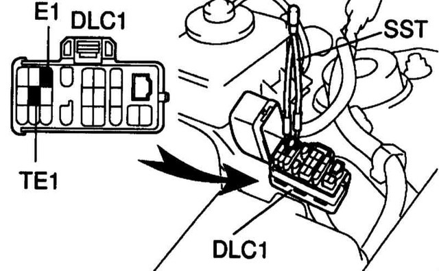
Self-diagnosis codes are read by the number of flashes of the “CHECK ENGINE” indicator with closed “TE1” – “E1” terminals of the DLC1 connector under the hood
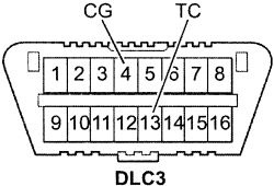
“TC” – “CG” DLC3 connector under the dashboard and the ignition on.
12 – Crankshaft Position Sensor (P0335)
13 – Crankshaft Position Sensor (P0335, P1335)
14 – Ignition system, coil number 1 (P1300) and number 4 (P1315)
15 – Ignition system, coil №2 (P1305) and №3 (P1310)
16 – Automatic Transmission Control System
18 – VVT-i system – phases (P1346)
19 – Accelerator pedal position sensor (P1120)
19 – Accelerator pedal position sensor (P1121)
21 – Oxygen sensor (P0135)
22 – Coolant temperature sensor (P0115)
24 – Intake air temperature sensor (P0110)
25 – Oxygen sensor – lean signal (P0171)
27 – Oxygen sensor №2
31 – Absolute pressure sensor (P0105, P0106)
34 – Turbocharging system
35 – Turbo-supercharging pressure sensor
36 – CPS Sensor (P1105)
39 – VVT-i System (P1656)
41 – Throttle Position Sensor (P0120, P0121)
42 – Vehicle speed sensor (P0500)
43 – Starter Signal
47 – Position sensor additional throttle
49 – Fuel Pressure Sensor (D-4) (P0190, P0191)
51 – Breaker Status
52 – Knock Sensor (P0325)
53 – Knock signal
55 – Knock sensor №2
58 – Drive SCV (D-4) (P1415, P1416, P1653)
59 – VVT-i signal (P1349)
71 – EGR System (P0401, P0403)
78 – fuel pump (D-4)
89 – ETCS Drive (P1125, P1126, P1127, P1128, P1129, P1633)
92 – Cold start nozzle (D-4) (P1210)
97 – Injectors (D-4) (P1215)
98 – Vacuum sensor in the vacuum brake booster (C1200)
Automatic:
Self-diagnosis codes are read by the number of flashes of the “O / D OFF” indicator with closed outputs
“TC” – “CG” (13-4) of the DLC3 connector under the dashboard and the ignition on
(at the same time, upshift activation must be allowed – “O / D OFF” is not lit).
11 – Norm
37 – Automatic input speed sensor (P1705)
38 – Automatic Transmission Fluid Temperature Sensor
42 – Speed sensor (or output shaft speed sensor) (Р0500)
44 – Speed sensor (or speed sensor rear output shaft)
46 – Solenoid pressure control hydroaccumulator (R1765)
61 – Speed sensor (or front output shaft speed sensor)
62 – Solenoid number 1 (P0753)
63 – Solenoid number 2 (R0758)
64 – Solenoid of the torque converter lock-up clutch (Р0773)
67 – Automatic input speed sensor
68 – Torque Converter Clutch Control Solenoid
73 – Solenoid clutch locking center differential
ABS Diagnostics:
Read codes (DLC3 models) (OBD-II)
– Jump the leads “TC” (13) and “CG” (4) of the DLC3 connector.
– Turn on the ignition.
– After 4 seconds, read the code by the number of flashes of the indicator.
– Remove the jumper from the “TC” and “CG” terminals.
Reset codes (models with DLC3 connector)
– Jump the leads “TC” (13) and “CG” (4) of the DLC3 connector.
– Turn on the ignition.
– Press the brake pedal eight or more times in the interval of three seconds.
– The indicator should display the code of the norm (blink 2 times per second).
– Remove the jumper from the “TC” and “CG” terminals.
11 – relay e / m valve (open circuit)
12 – Valve e / m valve (short circuit in the circuit)
13 – Electric pump relay (open circuit)
14 – Electric pump relay (short circuit in the circuit)
21 – E / m valve front right wheel (open circuit or short circuit)
22 – O / m valve of the front left wheel (open circuit or short circuit)
23 – E / m valve of the rear right wheel (open circuit or short circuit)
24 – E / m valve of the left rear wheel (open circuit or short circuit)
31 – Front right wheel speed sensor (fault)
32 – Front left wheel speed sensor (malfunction)
33 – Rear right wheel speed sensor (malfunction)
34 – Rear left wheel speed sensor (malfunction)
41 – Battery voltage too high or too low
43 – Deceleration sensor (circuit fault)
44 – Deceleration sensor (open circuit or short circuit in the circuit)
49 – Brake light switch (open circuit)
51 – Electric power supply circuit (open circuit or short circuit in the circuit)
71 – Front right wheel speed sensor (low signal)
72 – Front left wheel speed sensor (low signal)
73 – Rear right wheel speed sensor (low signal)
74 – Rear left wheel speed sensor (low signal)
75 – Front right wheel speed sensor (wrong signal change)
76 – Front left wheel speed sensor (incorrect signal change)
77 – Rear right wheel speed sensor (incorrect signal change)
78 – Rear left wheel speed sensor (wrong signal change)
79 – Deceleration sensor (malfunction)
About SRS
The self-diagnostic codes are read in the same way as the number of flashes of the “SRS” indicator with the closed “TC” – “CG” (13-4) terminals of the DLC3 connector under the dashboard and the ignition on.
Erasing codes should occur when the ignition is turned off.
If codes remain, it is necessary to carry out the cleaning procedure:
– connect two wires to the terminals “TC” and “AB”
– turn on the ignition and wait at least 6 seconds
– alternately, once a second, short to ground the terminals “TC” and “AB” (the pause between the closure is less than 0.2 seconds)
– after the third closure of the output “TC” indicator should flash with a high frequency – it means the codes are erased.
11 – Driver’s igniter PB (short to ground)
12 – Driver’s igniter PB (short to power)
13 – Driver’s igniter PB (circuit closure)
14 – Driver’s igniter PB (open circuit)
15 – Front right SRS sensor (short or open circuit)
15 – SRS front right sensor (short to ground or power)
16 – Front-left sensor SRS (short circuit or open circuit)
16 – Front Left SRS Sensor (short to ground or power)
31 – SRS control unit malfunction
51 – Passenger PB igniter (short to ground)
52 – Passenger PB igniter (short to power)
53 – Passenger PB igniter (short circuit in the circuit)
54 – Passenger PB igniter (open circuit)
61 – Driver Belt Pretensioner Igniter (short to ground)
62 – Driver belt pretensioner igniter (short to power)
63 – Driver Belt Pretensioner Igniter (Short Circuit)
64 – Driver Belt Tensioner Igniter (open circuit)
71 – Passenger Pretensioner Igniter (short to ground)
72 – Passenger belt pretensioner igniter (short to power)
73 – Passenger belt pretensioner igniter (short circuit)
74 – Passenger belt pretensioner igniter (open circuit)
DIAGNOSIS Toyota Connector Information
The Toyota injection system up to the year 98 has a DLC1 diagnostic plug. Usually it is located under the hood on the left and is a box with the inscription “DIAGNOSIS”.
E1
This is the “mass”. Earth.
B +
“Plus” battery. Appears when the ignition is turned on.
Ign-
Switch output – for a remote tachometer.
TE1
Conclusion for reading EFI system codes.
Diagnostics: “Normal mode”
Take any wire (or better low-power light-probe) and close the terminals “TE1” and “E1” (DLC No.1 or DLC No.2). In the “old” systems “T” or “TE”. After that, turn on the ignition, watch the light “CHECK” (light with the image of the engine, it is also “MIL”). Codes can be read by connecting the LED to the “W”.
Automatic self-diagnosis codes are read by the number of flashes of the “O / D OFF” indicator with closed outputs “TE1” – “E1”, while the overdrive must be enabled.
TE2
Diagnostics: “Test mode”
Accumulation of codes in this mode occurs when the contacts “E1” and “Te2” are closed before switching on the ignition. After that, the car should drive about 15 km. After stopping, the engine is not jammed and the E1-Te1 contacts are connected at idle and codes are read. The jumpers are removed in reverse order.
W
Conclusion bulbs Check. Connecting a very low-power indicator light between “B +” and “W” duplicates the “Check Engine” light bulb on the instrument panel.
Ox
Oxygen sensor output. You can measure the voltage (and its change in time) on the sensor. If you connect an oscilloscope. Or high-resistance fast voltmeter.
Fp
Conclusion to measure or supply voltage to the fuel pump without starting the engine. Set the jumper B + – Fp. When the ignition is turned on, the fuel pump will start immediately.
Vf1
Vf-feedback voltage is the contact whose voltage is the result of computer analysis of the oxygen sensor and the system. Read the detailed layout on the website: “Lambda probe: Check American.”
Tc
It is used to read the self-diagnosis codes of additional devices of the vehicle (Tc E1 overlap in the connector causes the codes to be displayed by the ABS, SRS, TRC OFF and Hight control lamps).
Read ABS codes
Turn on the ignition.
Jump the leads “TC” and “E1” of the DLC1 connector.
Remove the jumper from the “WA” and “WB” terminals.
After 4 seconds, read the code by the number of flashes of the ABS indicator.
Remove the jumper from the “TC” and “E1” terminals.
Set the jumper on the “WA” and “WB” terminals.
Reset ABS codes
Turn on the ignition.
Perekhnite conclusions “TC” and “E1”
Press the brake pedal eight or more times in the interval of three seconds.
The indicator should display the code of the norm (blink 2 times per second).
Turn off the ignition.
Remove the jumper from the “TC” and “E1” terminals.
Make sure the ABS indicator goes off.
The SRS (Toyota) self-diagnostic codes are read in the same way as the number of flashes of the “SRS” indicator with the “TC” – “E1” outputs closed. Erasing codes should occur when the ignition is turned off. If codes remain, it is necessary to carry out the cleaning procedure.
The tire pressure monitoring system provides its own self-diagnosis. Codes are read in a standard way for Toyoty according to the number of flashes of the indicator when the ignition is on and the “TC” and “E1” terminals are closed. The removal of codes is done in the same way as erasing ABS codes.
4WS self-diagnostic codes are read using the same method as the engine fault codes, according to the number of flashes of the “4WS” indicator with closed “TC” – “E1” terminals of the DLC1 connector under the bonnet and the ignition on.
AB
Erasing SRS DTCs:
connect the two wires to the terminals “TC” and “AB”
turn on the ignition and wait at least 6 seconds
alternately, once a second, short to ground the “TC” and “AB” terminals (the pause between the closure is less than 0.2 second)
after the third closure of the output “TC” the indicator should flash with a high frequency – it means the codes are erased
Never erase the airbag malfunction code without checking and finding out the meaning!
Ts
It is intended for reading the self-diagnostic codes (checking voltage deviations) of the ABS and Traction Control System speed sensors, which cannot be detected by ordinary self-diagnostics.
Resetting tire pressure monitoring system
Resetting the tire pressure monitoring system and its pre-setting should be done after performing any work related to the replacement of wheels, tires or wheels (pressure in all four wheels must be properly adjusted).
models without installation button and with DLC1 connector
Turn on the ignition.
Jump the pins “TS” and “E1”
After 30 seconds, press the brake pedal and hold it until the system indicator flashes 3 times at 2-second intervals.
models with installation button and with DLC1 connector
The installation buttons have a distinctive shape and location – at the bottom of the instrument panel on the driver’s side.
Turn on the ignition.
Jump the pins “TS” and “E1”
Press the setting button and hold it until the system indicator blinks 3 times.
After this, in order for the system to maintain the correct settings, it is necessary to drive some distance.
TT
used when checking automatic transmissions. To check the automatic transmission – perekknut conclusions “E1-TT”
Vf2, CC2, Ox2
When the vehicle is equipped with two lambda probes, the contacts perform the same Vf1, CC0 and Ox1 functions for the second sensor.
OP1
reading immobilizer self-diagnosis codes.
Td
Disable Air Suspension System.
On vehicles with OBD-II for the domestic Japanese market, the DLC No.1 connector is installed, but there are no “Te1”, “Te2”, “W”, “Vf”, “Cco”, “Ox”, “Ign” contacts in it be careful!

 on Volvo Cars")

, Audi, Seat and Skoda")
 JCB Fault Codes List
 MAN TGA Fault codes list
 CHALLENGER Tractor Fault Codes DTC