Service technicians have no problem recognising breakdowns and carrying out machine diagnostics, John Deere Fault Codes List, plus they are familiar with equipment from a variety of manufacturers.
Troubleshooting
To save time and money, follow these seven rules for quick and accurate troubleshooting:
1. EXPLORE A NODE
In other words, do everything that depends on you. Study the operating instructions for the driver-mechanic, as well as this guide to know how the individual nodes work and how they function in the operating system.
Check the latest service information. Read it and keep it readily available. This data may contain information about the cause of the problem that you encountered and how to troubleshoot it.
2. TAKE A LOOK WITH A BODY
Ask the driver, as the vehicle drove, when the strip was marked.
Find out that it was not as usual in the work of the combine.
Also, find out whether any work has been done on the machine yourself. You may have found a problem with someone else, but you should be aware of the measures that have already been taken.
Find out how the combo was operated, and how often the maintenance was carried out.
A large number of malfunctions arise as a result of good yields and careless handling.
3. GET COMBINE IN WORK
If the combine can be operated, try to drive it by yourself. Do not rely on the word of the driver-mechanic, check everything.
Do the given data show the measuring instruments? If not, it is possible that the unit provided by the device is not very functional, or the measuring device is incorrect.
How does the Combine drive? Does it function too fast, too slowly, incorrectly, or does it not function in general?
Do you feel the pedal resistance? Do they fall asleep?
Is there a hangover or smoke?
Are there any unusual noises? If yes, then?
4. OCMOTPITE COMBINE
Get out of the cab and take a look at the combine.
Look, listen, understand – everything can help you in the error message.
Take a good look at all parts and assemblies.
Check the absence of welding defects, flat fixed parts, damaged
connections, worn or torn wires, etc.
Note down all faults while viewing.
5. COCTABLE LIST OF FUNCTIONAL PRODUCTS
On the basis of the data obtained during the execution of pp. 1 – 4, list the possible reasons for the break.
What did you find out when you looked at the combo?
What is the most possible reason?
6. MAKE YOUR FOOD
Look at the list of possible causes and determine which of them are most probable and which are easier to believe.
Take decisions, which of the possible reasons are most probable, and check them first.
7. POSSIBLE YOUR STAY
Before starting the repair, check your pins and make sure they are correct.
Some possible reasons for the breakage can be checked without further testing. Check these reasons.
A further check will check the list of possible reasons for the break, and the actual cause will soon be found.
After an accurate determination of the reason for the breakdown, the dismantling and repair of the unit is not a trivial matter.
Access to diagnostic codes and error addresses
Display of information on diagnostics on the display
An information sheet is available for each address. Description contains details
provision of information.
They are listed by operation, therefore, all addresses related to one type of information,
are given together. In a number of systems, one and the same bits of information can be found in two or more addresses.
The diagram contains symbols that describe the image on the information display:
• n – numeric value
• 1 – displayed as 1 or 0. This means ON or OFF, which according to the description of the address
• x – information in the position of this sign has no meaning.
• _ – Probl. Display on display is absent
Diagnostic error codes
Each diagnostic trouble code (DTC) has a specific priority. DTC priority depends on how the DTC is displayed for the driver:
• Priority 1 – Angle display 1 stops normal operation, and DTC appears on the screen. This indicates a malfunction, at the appearance of which it is necessary to stop the vehicle, immediately turn off the engine and eliminate the malfunction. Corner set display 1 shows DTC until the error has been cleared.
• Priority 2 – The indicator of diagnostics on the display of 1 corner stand turns on. It indicates a problem that needs to be checked immediately
• Priority 3 – DTCs are written to memory, but the combiner is not shown.
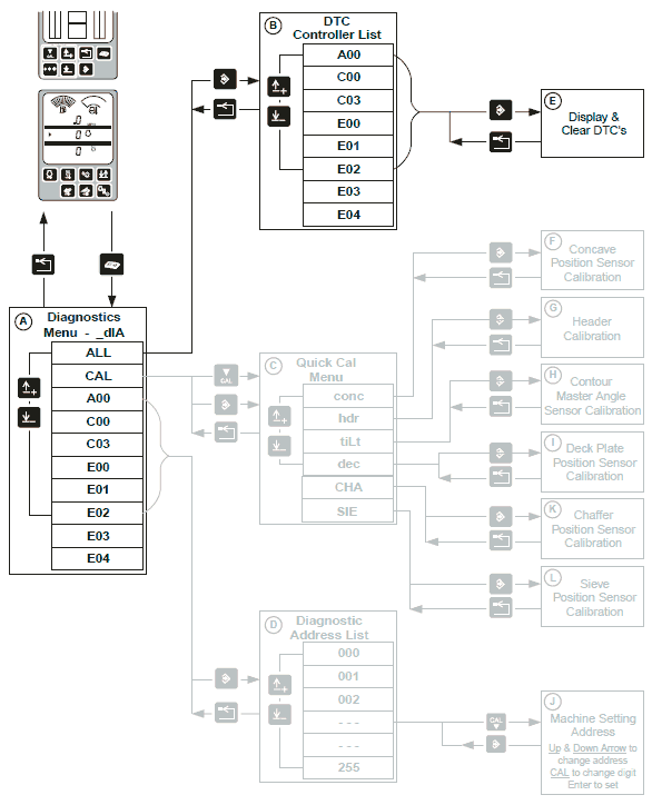
A — Diagnostics menu
B — Diagnostic codes
C — Quick Calibration Menu
D — List of addresses
E — Display and delete diagnostic trouble codes
F — Calibration of the recharge position sensor
G — Header Calibration
H — Calibration of the CONTOUR MASTER tilt sensor
I — Deck position sensor
J — Assigning Combine Addresses
K — Calibration of the position sensor
L — Calibration of the position sensor
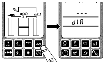
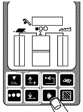
Press the diagnostics button. On the display of the 1st corner stand dIA will appear.
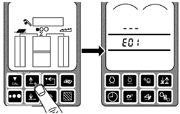
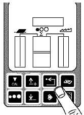
Press the buttons up or down until you reach the desired address. For example, E01 appears on the display of 1 corner stand.
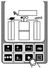
Press the input button.
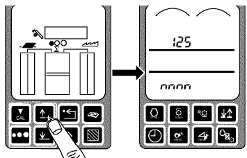
Press the buttons up or down until you reach the desired address. For example, 125 appears on the display of 1 corner rack.
Press the input button.
Information on this address can be seen on the display of 1 corner post.
If the address is of DISPLAY / MODIFY type, the content should be changed.
• The first available charge will flash (on the middle or bottom line, depending on the type
reapers)
• Press the arrow keys down and up on the display to increase or decrease the value of the blinking mark.
• When the flashing value is correct, press the calibration button to go to the next discharge
• Continue changing the value successively with one sign until the CPD1 display does not
will show the required value.
• Press the input button to write the new value into the memory
Return to normal operating mode:
• Press the return arrow twice to return to normal operation
• Turn ignition switch OFF / OFF
• At the next start of the car in the combo, this calibration information will be used
GREENSTAR Warning Messages and Error Codes
HARVEST DOC and HARVEST MONITOR presets:
Messages from the controller (s) are transmitted to the GREENSTAR display via the CAN bus.
The warning is shown on the GREENSTAR display as a full page message. Cancel
A warning message by pressing the button next to the word CANCEL will lead to its closing.
The CAUTION notices shown in section “G” of the GREENSTAR display will be
display it after canceling the warning message WARNING. If problem
installed or no more, the CAUTION warning in section “G” is larger
will not be displayed. Internal error codes HARVEST DOC and HARVEST MONITOR:
The error codes can be seen by pressing the INFO button on the GREENSTAR display. Then press the button
next to the GreenStar display, then click on the button next to the words Recent Problems. This page will display the codes with a short description that follows. To read the error code (s), click on the button next to the words Fault Codes.
ECU 000051.14
Propulsion system
EGR failure. Engine power is limited.
ECU 000094.17
Propulsion system
Fuel pressure is low. Check fuel supply and filters.
ECU 000094.18
Propulsion system
Fuel pressure is low. Engine power is limited. Check fuel supply and filters.
ECU 000097.16
Propulsion system
Water trap full. Engine power is limited. Drain the water trap.
ECU 000100.01
Propulsion system
Oil pressure is low. Engine power is limited. Check engine oil level.
ECU 000100.18
Propulsion system
Oil pressure is low. Engine power is limited. Check engine oil level.
ECU 000101.00
Propulsion system
Crankcase high pressure. Engine power is limited. Check the gas breakthrough filter.
ECU 000101.16
Propulsion system
Crankcase high pressure. Check the gas breakthrough filter.
ECU 000103.00
Propulsion system
Turbocharger speed is high. Engine power is limited. Reduce engine load and speed.
ECU 000105.00
Propulsion system
The air temperature in the intake manifold is high. Engine power is limited. Reduce engine load and speed. Check the cooling system for contamination.
ECU 000105.15
Propulsion system
The air temperature in the intake manifold is high. Reduce engine load and speed. Check the cooling system for contamination.
ECU 000105.16
Propulsion system
The air temperature in the intake manifold is high. Engine power is limited. Reduce engine load and speed. Check the cooling system for contamination.
ECU 000107.00
Propulsion system
Engine air filter clogged. Engine power is limited. Clean or replace the air filter.
ECU 000107.15
Propulsion system
Engine air filter clogged. Clean or replace the air filter.
ECU 000107.16
Propulsion system
Engine air filter clogged. Engine power is limited. Clean or replace the air filter.
ECU 000109.01
Propulsion system
Coolant pressure is low. Engine power is limited.
ECU 000109.17
Propulsion system
Coolant pressure is low. Check the pressure cap and leak tightness in the cooling system.
ECU 000109.18
Propulsion system
Coolant pressure is low. Engine power is limited. Check the pressure cap and leak tightness in the cooling system.
ECU 000109.31
Propulsion system
Coolant pressure is low. Check the pressure cap and leak tightness in the cooling system.
ECU 000110.00
Propulsion system
Engine coolant temperature is high. Engine power is limited. Reduce engine load and speed. Check the cooling system for contamination.
ECU 000110.15
Propulsion system
Engine coolant temperature is high. Reduce engine load and speed. Check the cooling system for contamination.
ECU 000110.16
Propulsion system
Engine coolant temperature is high. Engine power is limited. Reduce engine load and speed. Check the cooling system for contamination.
ECU 000110.17
Propulsion system
Engine coolant temperature is low. Check the cooling system.
ECU 000111.01
Propulsion system
Coolant level is low. Engine power is limited. Add coolant and inspect for leaks.
ECU 000111.07
Propulsion system
Coolant level circuit malfunction. The coolant level monitor is not working. Check coolant level.
ECU 000111.17
Propulsion system
Coolant level below service switch. Add coolant.
ECU 000111.18
Propulsion system
Coolant level is low. Add coolant and inspect for leaks.
ECU 000157.17
Propulsion system
The pressure in the fuel line is low at startup. Check filters and fuel level.
ECU 000168.01
Electrical system
Battery voltage is low.
ECU 000174.00
Propulsion system
Fuel temperature is high. Engine power is limited. Check the cooling system for contamination.
ECU 000174.16
Propulsion system
Fuel temperature is high. Check the cooling system for contamination.
ECU 000190.00
Propulsion system
High engine speed. Reduce engine speed.
ECU 000412.00
Propulsion system
EGR temperature is high. Engine power is limited. Reduce engine load and speed. Check the cooling system for contamination.
ECU 000412.15
Propulsion system
EGR temperature is high. Engine power is limited. Reduce engine load and speed. Check the cooling system for contamination.
ECU 000412.16
Propulsion system
EGR temperature is high. Engine power is limited. Reduce engine load and speed. Check the cooling system for contamination.
ECU 000641.16
Propulsion system
The temperature of the turbocharger drive is high. Reduce engine load and speed.
ECU 000651.02
Propulsion system
Fuel Injector Error No. 1. Engine speed is limited.
ECU 000651.13
Propulsion system
Fuel injector calibration error no. 1. Engine speed is limited.
ECU 000652.02
Propulsion system
Fuel Injector Error No. 2. Motor speed is limited.
ECU 000652.13
Propulsion system
Fuel injector calibration error no. 2. Motor speed is limited.
ECU 000653.02
Propulsion system
Fuel Injector Error No. 3. Motor speed is limited.
ECU 000653.13
Propulsion system
Fuel injector calibration error no. 3. Motor speed is limited.
ECU 000654.02
Propulsion system
Fuel Injector Error No. 4. Motor speed is limited.
ECU 000654.13
Propulsion system
Fuel injector calibration error no. 4. Motor speed is limited.
ECU 000655.02
Propulsion system
Fuel Injector Error No. 5. Engine speed is limited.
ECU 000655.13
Propulsion system
Fuel injector calibration error no. 5. Engine speed is limited.
ECU 000656.02
Propulsion system
Fuel Injector Error No. 6. Engine speed is limited.
ECU 000656.13
Propulsion system
Fuel injector calibration error no. 6. Engine speed is limited.
ECU 000970.31
Immobilizer system
Error authentication key or control unit. The engine control unit issued a command to turn off the engine. Check for the correct key for the machine. Restart the engine to try to recover the machine.
ECU 001075.02
Propulsion system
Failure of the electric fuel pump. Fuel system not working.
ECU 001075.04
Propulsion system
Malfunction of the electric fuel pump circuit. Fuel system not working.
ECU 001075.06
Propulsion system
Malfunction of the electric fuel pump circuit. Fuel system not working.
ECU 001075.09
Propulsion system
Failure of the electric fuel pump. Fuel system not working.
ECU 001110.31
Propulsion system
Stop to protect the engine.
ECU 001136.00
Propulsion system
The internal temperature of the engine control unit is high. Engine speed is limited.
ECU 001180.00
Propulsion system
The exhaust temperature is high. Engine power is limited. Reduce engine load and speed. Check the cooling system for contamination.
ECU 001180.16
Propulsion system
The exhaust temperature is high. Engine power is limited. Reduce engine load and speed. Check the cooling system for contamination.
ECU 001639.01
Propulsion system
Motor fan speed is low. Check fan drive system.
ECU 002630.00
Propulsion system
The charge air cooler temperature is high. Engine power is limited. Reduce engine load and speed. Check the cooling system for contamination.
ECU 002630.15
Propulsion system
The temperature at the outlet of the charge air cooler is high. Check the cooling system for contamination.
ECU 002630.16
Propulsion system
The temperature at the outlet of the charge air cooler is high. Engine power is limited. Reduce engine load and speed. Check the cooling system for contamination.
ECU 002790.16
Propulsion system
The temperature at the outlet of the turbocharger is high. Engine power is limited. Reduce engine load and speed.
ECU 003246.00
Exhaust filtration system
The temperature at the exhaust filter outlet is high. Engine power is limited.
ECU 003480.01
Exhaust filtration system
Error dosing fuel intake pressure. Active exhaust filter cleaning not available.
ECU 003480.03
Exhaust filtration system
Malfunction of the fuel metering pressure sensor circuit. Active exhaust filter cleaning not available.
ECU 003480.04
Exhaust filtration system
Malfunction of the fuel metering pressure sensor circuit. Active exhaust filter cleaning not available.
ECU 003482.16
Exhaust filtration system
Malfunction of fuel metering shut-off valve. Active exhaust filter cleaning not available.
ECU 003711.14
Exhaust filtration system
Exhaust filter inlet temperature not reached. Active exhaust filter cleaning not available.
ECU 003711.31
Exhaust filtration system
Exhaust filter inlet temperature not reached. Active exhaust filter cleaning not available.
ECU 003719.00
Exhaust filtration system
Exhaust filter blocked. Engine power is limited.
ECU 003719.13
Exhaust filtration system
The exhaust filtration system requires maintenance.
ECU 003719.14
Exhaust filtration system
Exhaust filter blocked. Engine power is limited. Initiate service cleaning.
ECU 003719.16
Exhaust filtration system
Exhaust filter blocked. Engine power is limited. Start cleaning the filter in the parked state on the engine settings page in accordance with the driver’s manual.
ECU 003720.15
Exhaust filtration system
The ash content in the exhaust filter is high. Perform filter maintenance.
ECU 003720.16
Exhaust filtration system
The ash content in the exhaust filter is high. Perform filter maintenance.
ECU 003936.00
Exhaust filtration system
Unexpected temperature in exhaust filter. Engine power is limited.
ECU 004766.16
Exhaust filtration system
Exhaust filter temperature higher than expected. Active exhaust filter cleaning not available.
ECU 004766.17
Exhaust filtration system
Error cleaning system. Cannot continue cleaning.
ECU 004766.18
Exhaust filtration system
Error cleaning system. Cannot continue cleaning.
ECU 004795.31
Exhaust filtration system
The exhaust filter is missing or severely damaged. Engine power is limited.
ECU 005018.00
Exhaust filtration system
Unexpected temperature in exhaust filter. Engine power is limited.
Diagnostic trouble codes of the engine control unit (ECU)
ECU 000097.03 – Engine system – The problem with the signal Water in the fuel. Arrange repair as soon as possible through a John Deere dealer.
ECU 000097.04
ECU 000097.16 – Engine water trap full – Remove water from water trap.
ECU 000100.01 – Engine oil pressure low – Check engine oil level. If the code returns, arrange for repair immediately through a John Deere dealer.
ECU 000100.03 – Engine system – The problem with the voltage signal of the oil pressure in the engine. Arrange repair as soon as possible through a John Deere dealer.
ECU 000100.04
ECU 000100.18
Engine oil pressure is low
Check engine oil level. If the code returns, arrange for repair as soon as possible through a John Deere dealer.
ECU 000100.31
Engine oil pressure
The gauge shows the oil pressure with the engine off. At the first opportunity, get a John Deere dealer repair.
ECU 000102.02
Engine system
A problem with the manifold air pressure sensor. At the first opportunity, get a John Deere dealer repair.
ECU 000102.03
ECU 000102.04
Engine system
Voltage malfunction for air pressure in the manifold. Arrange repair as soon as possible through a John Deere dealer.
ECU 000103.00
Engine system
Extremely high speed. When working at height to reduce the load on the engine. If the problem persists, arrange for repair as soon as possible through a John Deere dealer.
ECU 000103.05
ECU 000103.06
ECU 000103.08
ECU 000103.31
Engine system
Turbocharger speed error. Arrange repair as soon as possible through a John Deere dealer.
ECU 000105.00
Engine air temperature is high
The temperature of the intake air is high. Check coolant level. Inspect and clean the radiator. If the code returns, arrange for repair immediately through a John Deere dealer.
ECU 000105.03
ECU 000105.04
Engine system
Voltage malfunction for collector air temperature. Arrange repair as soon as possible through a John Deere dealer.
ECU 000105.15
Engine air temperature is high
The air temperature in the collector is higher than specified in the specification. Check coolant level. Inspect and clean the radiator. If the code returns, arrange for repair as soon as possible through a John Deere dealer.
ECU 000105.16
Engine air temperature is high
The air temperature in the reservoir is moderately high. Check coolant level. Inspect and clean the radiator. If the code returns, arrange for repair as soon as possible through a John Deere dealer.
ECU 000108.02
Engine system
A problem with a barometric pressure sensor. At the first opportunity, get a John Deere dealer repair.
ECU 000110.00
High engine coolant temperature
Check coolant level. Inspect and clean the radiator. If the code returns, arrange for repair immediately through a John Deere dealer.
ECU 000110.03
ECU 000110.04
Engine system
A problem with the input voltage of the engine coolant temperature sensor. Arrange repair as soon as possible through a John Deere dealer.
ECU 000110.15
High engine coolant temperature
Check coolant level. Inspect and clean the radiator. If the code is returned, arrange for repair at the first convenient opportunity through a John Deere dealer.
ECU 000110.16
High engine coolant temperature
Check coolant level. Inspect and clean the radiator. If the code returns, arrange for repair as soon as possible through a John Deere dealer.
ECU 000110.17
Low engine coolant temperature
Low engine coolant temperature. To warm up the engine. If the problem persists, arrange for repair as soon as possible through a John Deere dealer.
ECU 000157.03
ECU 000157.04
Engine system
The problem with the input voltage of the pressure sensor in the fuel line. Immediately arrange repairs through a John Deere dealer.
ECU 000157.10
Engine system
A pressure drop was detected in the fuel line. Arrange repair as soon as possible through a John Deere dealer.
ECU 000157.17
Engine system
The pressure in the fuel line does not increase. Arrange repair as soon as possible through a John Deere dealer.
ECU 000158.17
Engine system
Error disconnecting the power to the engine control unit. At the first opportunity, get a John Deere dealer repair.
ECU 000174.00
Fuel temperature is high
Fuel temperature is high. Check coolant level. Inspect and clean the radiator. Check if the code appears again. Immediately arrange repairs through a John Deere dealer.
ECU 000174.03
ECU 000174.04
Engine system
The problem with the input voltage of the fuel temperature sensor. Arrange repair as soon as possible through a John Deere dealer.
ECU 000174.16
Fuel temperature is high
Check coolant level. Inspect and clean the radiator and fuel cooler. If the code returns, arrange for repair as soon as possible through a John Deere dealer.
ECU 000189.00
No text
Engine speed decreases.
ECU 000190.00
High engine speed
The result of downshifts, reduce fuel flow. If the code returns, arrange for repair immediately through a John Deere dealer.
ECU 000237.02
ECU 000237.13
ECU 000237.31
Identification system
Invalid machine serial number. Arrange repair as soon as possible through a John Deere dealer.
ECU 000611.03
ECU 000611.04
Engine system
The problem with wiring nozzles with electronic control. Arrange repair as soon as possible through a John Deere dealer.
ECU 000627.01
Engine system
Problems with power supply nozzles with electronic control. Arrange repair as soon as possible through a John Deere dealer.
ECU 000629.12
Engine system
Problem with ECU memory. Arrange repair as soon as possible through a John Deere dealer.
ECU 000629.13
Engine system
ECU programming error. Immediately arrange repairs through a John Deere dealer.
ECU 000636.05
Engine system
A break in the cam sensor circuit. Arrange repair as soon as possible through a John Deere dealer.
ECU 000636.06
Engine system
Short circuit in the cam sensor circuit. Arrange repair as soon as possible through a John Deere dealer.
ECU 000647.05
Fan system
Short circuit or open circuit in the top output circuit 1 of the fan drive. Inspect the solenoid coil wires above the fan drive piston housing. Arrange repair as soon as possible through a John Deere dealer.
ECU 000651.02
ECU 000651.13
Engine system
The problem with the electronic fuel injection system. At the first opportunity, get a John Deere dealer repair.
ECU 000651.05
ECU 000651.06
ECU 000651.07
ECU 000652.02
ECU 000652.05
ECU 000652.06
ECU 000652.07
ECU 000652.13
ECU 000653.02
ECU 000653.05
ECU 000653.06
ECU 000653.07
ECU 000653.13
ECU 000654.02
ECU 000654.05
ECU 000654.06
ECU 000654.07
ECU 000654.13
ECU 000655.02
ECU 000655.05
ECU 000655.06
ECU 000655.07
ECU 000655.13
ECU 000656.02
ECU 000656.05
ECU 000656.06
ECU 000656.07
ECU 000656.13
Engine system
The problem with the electronic fuel injection system. Arrange repair as soon as possible through a John Deere dealer.
ECU 000676.03
ECU 000676.05
Engine system
Malfunction with the output of the glow plug relay. Arrange repair as soon as possible through a John Deere dealer.
ECU 001075.05
Fuel supply system
Short circuit / open circuit of the electric fuel priming pump on the fuel filter housing. At the first opportunity, get a John Deere dealer repair.
ECU 001110.31
Engine system
Stop to protect the engine. Arrange repair as soon as possible through a John Deere dealer.
ECU 001136.00
Engine system
High ECU temperature. Check ECU for air flow. If the problem persists, you should immediately arrange for repair through a John Deere dealer.
ECU 001136.16
Engine system
ECU internal temperature is high. Check ECU for air flow. If the problem persists, arrange for repair as soon as possible through a John Deere dealer.
ECU 001172.03
ECU 001172.04
Engine system
The problem with the input voltage of the temperature sensor at the input of the compressor. At the first opportunity, get a John Deere dealer repair.
ECU 001180.00
Engine system
The exhaust temperature is high. Immediately arrange repairs through a John Deere dealer.
ECU 001180.16
Engine system
Exhaust temperature higher than specified in the specification. Arrange repair as soon as possible through a John Deere dealer.
ECU 001347.03
ECU 001347.05
Engine system
Faulty pump control valve. Arrange repair as soon as possible through a John Deere dealer.
ECU 001347.07
Fuel filter
Malfunction associated with the regulation of pressure in the fuel line. Check the fuel filter, if the code reappears, then the John Deere dealer should repair the repair as soon as possible.
ECU 001569.31
Fuel – reduced power rating
There are circumstances leading to engine derating. At the first opportunity, get a John Deere dealer repair.
ECU 001639.01
ECU 001639.16
ECU 001639.18
ECU 002005.09
Fan system
Malfunction with fan speed signal. At the first opportunity, get a John Deere dealer repair.
ECU 002790.16
Engine system
High temperature at the outlet of the compressor. Arrange repair as soon as possible through a John Deere dealer.
Diagnostic Trouble Codes
Group A00-A00 – Diagnostic codes of malfunctions of the engine control unit
A00 00091.09 – CAN bus communication on opening the throttle door is not correct or not already given priority 3
A00 000094.03 – Voltage in the fuel pressure sensor (cc # 722) above the permissible limits – more than 4.75 V constant current – priority 1
A00 000094.04 – Voltage from the sensor (cc # 135) of the fuel pressure below the permissible limits – priority 1
A00 000094.10 – Replenishment of pressure in the magistral – priority 2
A00 000094.13 – The readings of the fuel pressure sensor are higher than expected.
A00 000094.17 – At the start, the pressure in the motor does not develop after an uninterrupted cranking of the crankshaft – priority 2
A00 000097.03 – Voltage of the signal of the water sensor in fuel (cc # 136) above the permissible limits – priority 2
A00 000097.04 – Voltage in the water sensor in fuel (cc # 136) below the permissible limits – priority 2
A00 000097.31 – Water supplied with fuel – priority 2
A00 000100.01 – The oil pressure sensor is disconnected after the set of revolutions above the crank speed – priority 1
A00 000100.04 – Oil pressure sensor closed after engine stop – priority 2
A00 000 105.00 – Engine air temperature above 100 ° C (212 ° F) – priority 1
A00 000105.03 – Voltage in the air temperature sensor in the engine manifold above the permissible limits – priority 2
A00 000105.04 – Voltage in the air temperature sensor in the engine manifold below the permissible limits – priority 2
A00 000105.16 – Engine air temperature above 88 ° C (190 ° F) (moderate heavy duty) – priority 2
A00 000107.00 – Air filter filling switch signals about air filter filling – priority 2
A00 000110.00 – Engine coolant temperature above 115 ° C (240 ° F) (the most difficult duty) – priority 1
A00 000110.00 – Engine coolant temperature above 120 ° C (248 ° F) (heaviest duty) – priority 1
A00 000110.03 – Voltage of the engine coolant temperature sensor above the permissible limits – priority 2
A00 000110.04 – Voltage of the engine coolant temperature sensor below permissible limits – priority 2
A00 000110.15 – Engine coolant temperature above 105 ° C (221 ° F) – priority 2
A00 000110.16 – Engine coolant temperature above 110 ° C (230 ° F) – priority 2
A00 000111.01 – The level of the cooling liquid is lower than the standard. Engine coolant temperature above 125 ° C (257 ° F) – priority 1
A00 000158.17 – The controller is not running properly – priority 2
A00 000174.03 – Voltage in the fuel temperature sensor in the engine above the permissible limits – priority 2
A00 000174.04 – Voltage in the fuel temperature sensor in the engine below the permissible limits – priority 2
A00 000174.16 – Fuel temperature in the engine above the normal range (over 65 ° C / 149 ° F) – priority 2
A00 000174.16 – Fuel temperature in the engine above the normal range (over 80 ° C / 176 ° F) – priority 2
A00 000611.03 – The driver of the cell has a short circuit to the battery in the guide to the cell – priority 1
A00 000611.04 – The driver has provided a short circuit to the mass in the guide to the fork – priority 1
A00 000620.03 – Internal (5-volt) constant voltage of the engine control unit out of range or too high – priority 2
A00 000620.04 – Internal (5-volt) constant voltage of the engine control unit out of range or too low – priority 2
A00 000627.01 – All current values on the display outside the standard – priority 2
A00 000636.02 – Electrical disturbances detected at the pump position sensor + (cc # 172) and / or the pump position sensor – (cc # 173) – priority 2
A00 000636.08 – No signal from the pump position sensor – priority 2
A00 000636.10 – Incorrect timing diagram of pulse tracking on the pump position sensor – priority 2
A00 000637.02 – At engine speed sensor + (cc # 174) and / or (cc # 175) electric noise is equipped – priority 2
A00 000637.07 – Incorrect position of the engine speed sensor and the pump position sensor – priority 2
A00 000637.08 – Missing signal from engine speed sensor – priority2
A00 000637.10 – Incorrect timing diagram of pulse tracking on the engine speed sensor – priority 2
A00 651.05 – Topcynk # 1 lower expected – priority 2
A00 000651.06 – Topcynk # 1 is too fast – priority 2
A00 000651.07 – Fuel supply to cylinder # 1 lower than expected – priority 2
A00 000652.05 – Topcynk # 2 below expected – priority 2
A00 000652.06 – Token # 2 is too fast – priority 2
A00 000652.07 – Fuel supply to cylinder # 2 lower than expected – priority 2
A00 000653.05 – Topcynk # 3 below expected – priority 2
A00 000653.06 – Topcynk # 3 is too fast – priority 2
A00 000653.07 – Fuel supply to cylinder # 3 lower than expected – priority 2
A00 000654.05 – Topcynk # 4 lower expected – priority 2
A00 000654.06 – Topcynk # 4 is too fast – priority 2
A00 000654.07 – Fuel supply to cylinder # 4 lower than expected – priority 2
A00 000655.05 – Topcynk # 5 below expected – priority 2
A00 000655.06 – Topcynk # 5 is too fast – priority 2
A00 000655.07 – Fuel supply to cylinder # 5 is lower than expected – priority 2
A00 000656.05 – Topcynk # 6 below expected – priority 2
A00 000656.06 – Topcynk # 6 is too fast – priority 2
A00 000656.07 – Fuel supply to cylinder # 6 lower than expected – priority 2
A00 000676.03 – Output signal (cc # 191) from the ignition spark plug heater is high, if the engine control unit does not supply power to the boiler 2
A00 000676.05 – The output signal (cc # 191) from the ignition spark plug heater is low, if the engine control unit supplies power to the boiler
A00 000931.11 – Gear pump signal (cc # 36) indicates the presence of a disconnect or short circuit – priority 2
A00 001080.03 – Overvoltage supply of the pressure sensor in the magistral (cc # 721) – priority 1
A00 001080.04 – Undervoltage supply of the pressure sensor in the magistral (cc # 721) – priority 1
A00 001347.03 – The driver has detected an undershoot in the circuit of the solenoid pump (cc # 178) – priority 1
A00 001347.05 – The driver has detected an undershoot in the pump solenoid circuit (cc # 176) – priority 1
A00 001347.05 – The driver has detected an undershoot in the pump solenoid circuit (cc # 176) – priority 2
A00 001347.07 – The pressure control system in the magistral cannot get the correct pressure in the magistral – priority 2
A00 001347.10 – Solenoid 1 pump does not provide the expected fuel supply – priority 2
A00 001348.05 – The driver has detected an undershoot in the circuit of the solenoid pump 2 (cc # 179) – priority 2
A00 001348.10 – Pump solenoid 2 does not provide the expected fuel supply – priority 2
A00 001569.31 – Engine protection – power reset due to other faults – priority 2
A00 002000.13 – Weakening the protection of the engine control unit – priority 1
Group C00-C00 – Diagnostic codes of malfunctions of the control unit in the armrest
C00 000158.04 – Control circuit power supply (cc # 023) below 10.5 V DC – priority 3
C00 000 170.03 – Overvoltage at the CLIMATRAK sensor, air temperature in the cab – more than 4.8 V DC – priority 3
C00 000 170.04 – Undervoltage at the CLIMATRAK sensor, air temperature in the cab – less 0.1 V of the constant current – priority 3
C00 000172.03 – Overvoltage on the CLIMATRAK sensor of the external air temperature – more than 4.8 V constant current priority 3
C00 000172.04 – Undervoltage at the CLIMATRAK sensor of the external air temperature – less 0.1 V constant current – priority 3
C00 000190.09 – Lack of CAN communication from engine control – Engine speed – priority 3
C00 000605.04 – Ha CLIMATRAK low pressure switch (cc # 914) 12 V DC – priority 3
C00 000627.03 – Delay voltage (cc # 006) above 16 V DC – priority 1
C00 000627.04 – Delay voltage (cc # 006) below 10.5 V DC – priority 3
C00 000628.12 – The controller cannot exit the block program of the initial download – priority 1
C00 000630.11 – The controller did not hold the EEPROM test on power-up – priority 1 C00 000639.19 – CAN bus messages were not correctly assigned or priority 3 was accepted
C00 000875.04 – CAN bus communication with left-hand control – CLIMATRAK clutch signal (cc # 913) 12 V DC – priority 3
C00 001490.08 – Feeder chamber speed unknown – priority 2
C00 001498.11 – Signal from the header switch on switch indicates opening, short circuit, high voltage or high temperature – priority 3
C00 001499.11 – The signal from the switch on of the heater indicates opening, short circuit, high voltage or high temperature – priority 3
C00 001499.12 – Schedule of malfunctions of turning on the unit, priority 2 has been detected
C00 001504.11 – Seat switch was closed within 6 hours in a row – priority 1
C00 001547.03 – CLIMATRAK Overvoltage on the temperature sensor inside the controller – more than 4.47 V constant current priority 3
C00 001547.04 – CLIMATRAK Undervoltage at the temperature sensor inside the con- ditioner – below 0.1 V constant current priority 3
C00 001548.03 – CLIMATRAK Overvoltage on the outlet air temperature sensor – more than 4.8 V constant current priority 3
C00 001548.04 – CLIMATRAK Undervoltage at the outlet air temperature sensor – below 0.1 V constant current priority 3
C00 001549.07 – CLIMATRAK Positioning the water valve more than 30% different from the given priority 3
C00 200017.09 – No CAN bus communication (s) from corner post control unit – priority 3
C00 200018.09 – No CAN bus communication (s) from the left control unit – priority 3
C00 200 201.11 – Incorrect signals from the power switch – priority 3
C00 200202.11 – Incorrect signals from the power switch – priority 3
Group C03 — C03 – Diagnostic codes of malfunctions of the corner stack control unit
C03 000096.09 – Lack of CAN communication from the right control unit – fuel level – priority 3
C03 000110.09 – Lack of CAN communication from engine control unit – engine coolant temperature – priority 3
C03 000190.09 – Lack of CAN communication from engine control – Engine speed – priority 3
C03 000627.03 – Delay voltage (cc # 006) above the permissible limits – above 16 B constant current – priority 3
C03 000628.12 – The controller cannot exit the block program of the initial download – priority 1
C03 000630.11 – EEPROM did not pass test on power-up – priority 1
C03 000639.19 – CAN bus messages were not assigned correctly or priority 3 was accepted
C03 001079.03 – Overvoltage on the recharge position sensor – more than 5.5 V constant current – priority 3
C03 001079.04 – Undervoltage on the trim position sensor – less than 4.5 V DC.
C03 001486.03 – Voltage of the recharge position sensor too high – more than 4.5 V DC – priority 3
C03 001486.04 – Voltage of the recharge position sensor too low – less than 0.5 V DC current – priority 3
C03 001487.03 – Overvoltage of the blinking light – more than 4.5 V DC – priority 3
C03 001487.04 – Undervoltage of the blinking light – less than 0.5 V DC – priority 3
C03 001492.08 – Signal from the driver of the interior light in the cab has opened a circuit breaker, short circuit, high voltage or high temperature
C03 001493.09 – Lack of CAN communication from main waste sensor – waste volume – priority 3
C03 001500.11 – The switch on block 1 of the corner post display does not work for more than 30 seconds – priority 3
C03 001501.11 – The switch on the block 2 of the corner post display does not work for more than 30 seconds, priority 3
C03 001502.11 – The switch on the block 3 of the corner post display does not work for more than 30 seconds – priority 3
C03 001503.09 – Lack of CAN bus communication from control unit in armrest – Status of armrest switch – priority 3
C03 001510.09 – Lack of CAN communication from the right control unit – Temperature on the combo – priority 3
C03 001511.09 – Lack of CAN communication from the right control unit – Loss of grain – priority 3
C03 001515.09 – Lack of CAN communication from header control unit – Header settings – priority 3
C03 001552.03 – CLIMATRAK Overvoltage for setting the temperature – more than 4.5 V DC – priority 3
C03 001552.04 – CLIMATRAK Reduced voltage for setting the temperature – below 0.5 V DC – priority 3
C03 001552.13 – CLIMATRAK Temperature setting not calibrated – priority 3
C03 001553.03 – CLIMATRAK Overvoltage of the clean fan speed control system – more than 4.5 V constant current priority 3
C03 001553.04 – CLIMATRAK Undervoltage of the fan speed control system – lower 0.5 V constant current priority 3
C03 001553.13 – CLIMATRAK Cleaning fan speed setting not calibrated – priority 3
C03 001565.09 – Lack of CAN communication from the control unit in the armrest – Status of starting the engine and the header – priority 3
C03 001567.09 – Lack of CAN bus communication from header control unit – Control mode – priority 3
C03 100 100.09 – Lack of CAN bus communication from the left control unit – System data – priority 3
C03 100101.09 – Lack of CAN bus communication from the left control unit – System data – priority 3
C03 100106.11 – Switch on block 4 of the corner post display does not work for more than 30 seconds – priority 3
Group E00-E00 – Diagnostic codes of malfunctions of the main waste sensor
E00 000190.09 – Lack of CAN communication from engine control unit – Engine speed – priority 3
E00-E00 000628.12 – The controller cannot exit the block program of the initial download – priority 2
E00-E00 000630.11 – EEPROM failed test on power up 2
E00-E00 000639.09 – The main waste management unit does not receive the modern CAN bus – priority 3
E00-E00 000639.19 – CAN bus messages were not assigned correctly or priority 3 was accepted
E00-E00 001493.11 – Fault in the waste system – priority 3
E00-E00 001493.15 – Calibration of the waste system oversized – priority 3
E00-E00 001493.17 – Calibration of the waste system is undershot – priority 3
E00-E00 001494.08 – Recognized photo element in the main waste sensor – priority 3
E00-E00 001 494.11 – Main waste sensor malfunction – priority 3
E00-E00 001 495.08 – Rediscovery of photo elements in the secondary waste sensor priority 3
E00-E00 001495.11 – Main waste sensor malfunction – priority 3
E00-E00 001 496.07 – Missing waste electric motor – priority 3
E00-E00 001511.09 – Lack of CAN communication from the right control unit – Grain size – priority 3
E00-E00 001565.09 – Lack of CAN communication from the control unit in the armrest – the processor and the header are on – priority 3
E00-Group E01-E01 – Diagnostic codes of malfunctions of the header control unit
E01 000084.09 – Lack of CAN bus communication from corner stack control unit – Wheel speed – priority 3
E01 000190.09 – Lack of CAN communication from engine control unit – Engine speed – priority 3
E01 000627.03 – Overvoltage on the controller – more than 16 V DC – priority 1
E01 000628.12 – The controller cannot exit the block program of the initial download – priority 1
E01 000630.11 – The system is not calibrated or the EEPROM did not stand the power-on test – priority 3
E01 000639.13 – The header control unit does not receive the current communication of the CAN multi-bus system – priority 3
E01 000639.19 – CAN bus messages were not correctly assigned or accepted – priority 2
E01 001079.03 – Overvoltage at the height sensor (cc # 481) – more than 5.25 V DC – priority 2
E01 001079.04 – Undervoltage at the height sensor (cc # 481) – less than 4.75 V DC – priority 2
E01 001080.03 – Overvoltage at height sensor 2 (cc # 471) – more than 5.25 V constant current priority 2
E01 001080.04 – Undervoltage at height sensor 2 (cc # 471) – less than 4.75 V constant current priority 2
E01 001515.13 – Active elevation control or CONTOUR MASTER not calibrated for a specific external header – priority 2
E01 001516.13 – The system of the “floating” mode of the header is not calibrated for a specific external header – priority 2
E01 001518.02 – The voltage in the circuit (codes 436, 487, 488 and 489) has been changed during the operation of the active control system in the automatic mode – priority 3


 JCB Fault Codes List
 MAN TGA Fault codes list
 Fault Codes and diagnostic code Information for Caterpillar Control