Service technicians have no problem recognising breakdowns and carrying out machine diagnostics, Error Codes TOYOTA DTC DIAGNOSTICS, plus they are familiar with equipment from a variety of manufacturers.
After installing the on-board computer, I received an error of 1105. I could not immediately find what it meant. I pretty much poked around the Internet and found the same codes. I had a wire break in the CPS sensor and “CHECK ENGINE” did not burn, I do not know why. Cured the wire and the machine began to behave differently. That’s actually the very codes that we need to use!
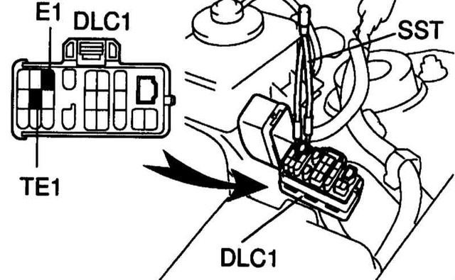
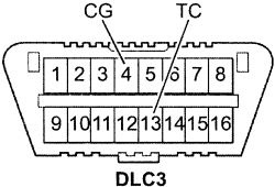
ENGINE: The self-diagnosis codes are read by the number of flashes of the “CHECK ENGINE” indicator when the terminals “TE1” – “E1” of the DLC1 connector are closed under the hood or “TC” – “CG” of the DLC3 connector under the dashboard and the ignition on.
DLC3 or OBD2
12 – Crankshaft Position Sensor (P0335)
13 – Crankshaft Position Sensor (P0335, P1335)
14 – Ignition system, coil No. 1 (P1300) and No. 4 (P1315)
15 – Ignition system, coil No. 2 (P1305) and No. 3 (P1310)
16 – Automatic transmission control system
18 – VVT-i system – phases (P1346)
19 – Accelerator pedal position sensor (P1120)
19 – Accelerator pedal position sensor (P1121)
21 – Oxygen sensor (P0135)
22 – Coolant temperature sensor (P0115)
24 – Intake air temperature sensor (P0110)
25 – Oxygen sensor – poor mix signal (P0171)
27 – Oxygen sensor # 2
31 – Absolute pressure sensor (P0105, P0106)
34 – Turbocharger system
35 – Turbocharger pressure sensor
36 – CPS sensor (P1105)
39 – VVT-i system (P1656)
41 – Throttle Position Sensor (P0120, P0121)
42 – Vehicle speed sensor (P0500)
43 – Starter signal
47 – Additional throttle position sensor
49 – Fuel pressure sensor (D-4) (P0190, P0191)
51 – Status of switches
52 – Knock sensor (P0325)
53 – Detonation signal
55 – Knock Sensor No.2
58 – Drive SCV (D-4) (P1415, P1416, P1653)
59 – Signal VVT-i (P1349)
71 – EGR system (P0401, P0403)
78 – injection pump (D-4)
89 – Drive ETCS (P1125, P1126, P1127, P1128, P1129, P1633)
92 – Cold start nozzle (D-4) (P1210)
97 – Nozzles (D-4) (P1215)
98 – The vacuum gauge in the vacuum amplifier of brakes (C1200)
Automatic transmission: The self-diagnosis codes are read by the number of flashes of the “O / D OFF” indicator when the terminals are closed “TC” – “CG” (13-4) of the DLC3 connector under the dashboard and the ignition on (In this case, the upshift is to be enabled – “O / D OFF” is not lit).
11 – Norm
37 – Input speed sensor for automatic transmission (P1705)
38 – The gauge of temperature of a working liquid АКПП
42 – Speed sensor (or output speed sensor) (P0500)
44 – Speed sensor (or rear output speed sensor)
46 – Pressure accumulator pressure control solenoid (P1765)
61 – Speed sensor (or front output speed sensor)
62 – Solenoid No. 1 (P0753)
63 – Solenoid No. 2 (P0758)
64 – Torque converter lock solenoid (P0773)
67 – Input speed sensor for automatic transmission
68 – Torque converter clutch control solenoid
73 – Interaxle differential lock solenoid
Diagnosis of the ABS system: Reading codes (models with DLC3 connector) (OBD-II)
– Connect the “TC” (13) and “CG” (4) terminals of the DLC3 connector.
– Switch on the ignition.
– After 4 seconds, read the code by the number of indicator flashes.
– Remove the jumper from the terminals “TC” and “CG”.
Reset codes (models with DLC3 connector)
– Connect the “TC” (13) and “CG” (4) terminals of the DLC3 connector.
– Switch on the ignition.
– Depress the brake pedal eight or more times in the interval of three seconds.
– The indicator should output the normal code (flashing 2 times per second).
– Remove the jumper from the terminals “TC” and “CG”.
11 – Relay e / m valve (open circuit)
12 – Relay e / m valve (short circuit in the chain)
13 – Electropump relay (open circuit)
14 – Electropump relay (short circuit in the circuit)
21 – Front left right-hand wheel (open or short-circuited)
22 – E / m front left-hand wheel valve (open or short-circuited)
23 – E / m rear right wheel valve (open or short circuit)
24 – E / m the valve of the rear left wheel (breakage or short circuit)
31 – Front right-wheel speed sensor (fault)
32 – Front left wheel speed sensor (fault)
33 – Rear right wheel speed sensor (fault)
34 – Rear left wheel speed sensor (fault)
41 – Battery voltage too high or too low
43 – Deceleration sensor (fault in the circuit)
44 – Deceleration sensor (open or short circuit in the circuit)
49 – Brake light switch (open circuit)
51 – Power supply circuit of the electric pump (open or short circuit in the circuit)
71 – Right front wheel speed sensor (low signal level)
72 – Left Front Wheel Speed Sensor (Low Signal)
73 – Rear right-wheel speed sensor (low signal level)
74 – Left rear wheel speed sensor (low signal level)
75 – Front right-hand wheel speed sensor (incorrect signal change)
76 – Front left wheel speed sensor (incorrect signal change)
77 – Rear right wheel speed sensor (incorrect signal change)
78 – Rear left wheel speed sensor (incorrect signal change)
79 – Deceleration sensor (malfunction)
About SRS
The self-diagnosis codes are read out in the same way as the others, in terms of the number of flashes of the “SRS” indicator when the terminals “TC” – “CG” (13-4) of the DLC3 connector under the dashboard are closed and the ignition is switched on.
Erasing codes must occur when the ignition is switched off. If the codes are saved, you need to perform the cleaning procedure:
– connect two wires to the terminals “TC” and “AB”
– switch on the ignition and wait at least 6 seconds
– alternately, once per second, connect the terminals “TC” and “AB” (the pause between the closures is less than 0.2 seconds)
– after the third closing of the output “TC” the indicator should blink at a high frequency – the codes are erased.
11 – Driver’s ignitor PB (short to ground)
12 – Driver’s Igniter (short to power)
13 – Driver’s Igniter (short circuit in the circuit)
14 – Driver’s Igniter (break in the chain)
15 – Front right SRS sensor (short circuit or open circuit)
15 – Front right SRS sensor (short to ground or power)
16 – Front left SRS sensor (short circuit or open circuit)
16 – Front left SRS sensor (short to ground or power)
31 – Malfunction of the SRS control unit
51 – Passenger’s igniter PB (short to ground)
52 – Passenger’s igniter PB (short to power)
53 – Passenger’s igniter PB (short circuit in the circuit)
54 – Passenger Igniter (break in the chain)
61 – Driver belt pretensioner ignition (short to ground)
62 – Driver’s belt pretensioner (short to power)
63 – Driver’s belt pretensioner (short circuit in chain)
64 – Driver belt pretensioner ignition (open circuit)
71 – Passenger belt pre-tensioner igniter (short to ground)
72 – Passenger belt pre-tensioner igniter (short to power)
73 – Passenger belt pretensioner ignition (short circuit in the chain)
74 – Passenger belt pre-tensioner igniter (break in chain)
Information on the DIAGNOSIS connector Toyota
The Toyota injection system up to 98 years has a diagnostic socket DLC1. Usually it is under the hood to the left and represents a box with the inscription “DIAGNOSIS”.
E1
This is the “mass”. Earth.
B +
A “plus” battery. Appears when the ignition is switched on.
IGN-
The output of the switch is for the remote tachometer.
TE1
Output for reading EFI system codes.
Diagnostics: “Normal mode”
Take any wire (or preferably a low-power light bulb-probe) and close the conclusions of “TE1” and “E1” (DLC No.1 or DLC No.2). In the “old” systems “T” or “TE.” After that, after turning on the ignition, watch the “CHECK” lamp (the engine lamp, it’s “MIL”). Codes can be read by connecting the LED to “W”.
The self-diagnosis codes of the automatic transmission are read by the number of flashes of the indicator “O / D OFF” with the closed terminals “TE1” – “E1”, and the overdrive should be switched on.
TE2
Diagnostics: “Test mode”
Accumulation of codes in this mode occurs when the contacts “E1” and “Te2” are closed before switching on the ignition. After that, the car should drive about 15 km. After stopping the engine does not muffle and at idle the contacts E1-Te1 are connected and codes are read out. Remove the jumpers in the reverse order.
W
Bulb output Check. The connection of a very low-power indicator light between “B +” and “W” duplicates the “Check Engine” light on the instrument panel.
Ox
Oxygen sensor output. It is possible to measure the voltage (and its variation in time) on the sensor. If you connect an oscilloscope. Or high-resistance fast voltmeter.
Fp
Output for measuring or energizing a gasoline pump without starting the engine. Set the jumper B + – Fp. When the ignition is switched on, the gasoline pump will start working immediately.
Vf1
Vf-feedback voltage is the contact whose voltage is the result of the computer’s analysis of the oxygen sensor and the system. Read the detailed layout on the website: “Lambda probe: Testing in American.”
Tc
Used to read the self-diagnosis codes for additional vehicle devices (Tc E1 in the connector causes the codes to be indicated by ABS, SRS, TRC OFF and Hight control).
Reading ABS codes
Turn the ignition on.
Connect the leads “TC” and “E1” of the DLC1 connector.
Remove the jumper from the “WA” and “WB” terminals.
After 4 seconds, read the code for the number of flashes of the ABS indicator.
Remove the jumper from the terminals “TC” and “E1”.
Set the jumper on the “WA” and “WB” terminals.
Resetting ABS codes
Turn the ignition on.
Bring the conclusions of “TC” and “E1”
Press the brake pedal eight or more times in the interval of three seconds.
The indicator should output the normal code (flashing 2 times per second).
Turn the ignition off.
Remove the jumper from the terminals “TC” and “E1”.
Make sure that the ABS indicator goes out.
The SRS (Toyota) self-diagnosis codes are read in the same way as the number of “SRS” indicator flashes with the closed terminals “TC” – “E1”. Erasing codes must occur when the ignition is switched off. If the codes are saved, a cleaning procedure must be carried out.
The tire pressure monitoring system provides its own self-diagnosis. The codes are read in the standard way for Toyot’s by the number of indicator flashes with the ignition on and the closed terminals “TC” and “E1”. Removal of codes is carried out in the same way as deleting the codes of the ABS system.
The 4WS self-diagnosis codes are read in the same way as the engine trouble codes according to the number of flashes of the “4WS” indicator when the terminals “TC” – “E1” of the DLC1 connector under the hood are closed and the ignition is switched on.
AB
Erasing SRS DTCs:
connect two wires to the terminals “TC” and “AB”
Turn the ignition on and wait at least 6 seconds.
alternately, once per second, connect the terminals “TC” and “AB” (the pause between the closures is less than 0.2 seconds)
after the third closing of the output “TC”, the indicator should blink at a high frequency – the codes are erased
Never erase the airbag defect code without checking and figuring out the value!
Ts
It is intended for reading the codes of self-test (check of voltage deviations) of speed sensors ABS and Traction Control System, which can not be detected by usual self-diagnostics.
Resetting the tire pressure monitoring system
Resetting the tire pressure monitoring system and its pre-setting should be done after any work related to the replacement of wheels, tires or disks (the pressure in all four wheels must be adjusted correctly).
model without a setting button and with a DLC1 connector
Turn the ignition on.
Connect the leads “TS” and “E1”
After 30 seconds, depress the brake pedal and hold it until the system indicator blinks 3 times with an interval of 2 seconds.
Models with installation button and with DLC1 connector
The setting buttons differ in their characteristic shape and arrangement – in the lower part of the instrument panel on the driver’s side.
Turn the ignition on.
Connect the leads “TS” and “E1”
Press and hold the setting button until the system indicator blinks 3 times.
After this, in order for the system to keep the correct settings, it is necessary to travel a certain distance.
TT
Used for checking automatic transmissions. To check the automatic transmission – to interconnect the “E1-TT”
Vf2, CC2, Ox2
When the vehicle is equipped with two lambda probes, the contacts perform similar functions for Vf1, CC0 and Ox1 for the second sensor.
OP1
reading the codes for self-diagnosis of the immobilizer.
TD
disabling the Air Suspension System.
On vehicles with OBD-II, the DLC No.1 connector is installed for the domestic Japanese market, but there are no contacts for Te1, Te2, W, Vf, Cco, Ox, Ign – be careful!
The diagnosis tool Error Codes TOYOTA DTC DIAGNOSTICS for trucks provides different possibilities such as information on the use and location of the connectors, detection and description of errors, activation of the fan, compression test and other components, system data information and more.


 JCB Fault Codes List
 Fault Codes and diagnostic code Information for Caterpillar Control
 MAN TGA Fault codes list